Variable Frequency Drives Explained - VFD Basics IGBT inverter
3.19M views2680 WordsCopy TextShare
The Engineering Mindset
Variable Frequency Drives Explained - VFD basics. In this video we take a look at variable frequency...
Video Transcript:
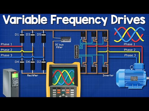
[Applause] hey there guys paul here from the engineering mindset. com in this video we're going to be looking at vfds we'll be starting from the basics to understand how they work remember electricity is dangerous and can be fatal you should be qualified and competent to carry out any electrical work if you work in hvac then you need to check out the inverter compressors by denfos who have kindly sponsored this video when used in combination with variable speed technology like the vfds we're going to cover in today's video they make your entire hvac unit more efficient saving you and your customers money if you want to learn more danfoss has several e-lessons and case stories for you to check out you can find links those in the video description down below vfd stands for variable frequency drive and they look something like this you might also hear them referred to with ac drives or variable speed drives and that's because they are used to control the rotational speed of an ac motor we find ac motors and vfds used in all industries but especially hvac for example we can find them used to control a compressor's speed in a refrigeration system and that allows us to closely match the cooling demand which will result in significant energy savings traditionally we would have had to use a fixed speed compressor now these simply just turn on and off and that results in poor control and higher inrush currents we also find them used to control things such as pumps and fans in hvac systems to allow us to unlock energy savings and improve performance and control the vfd unit is connected into the motor's electrical supply the unit can vary the frequency of the electricity being supplied to drive the motor and by varying this we can control the rotational speed of the motor therefore we have our variable frequency drive to understand how a vfd works we first need to understand some fundamentals of electricity there are two types of electricity and the first one we're going to look at is dc or direct current this is the simplest type and we get this from batteries solar panels etc you can think of dc like a river with a current of water flowing in just one direction with dc the electrons just flow in a single direction now i'm animating this using electron flow which is from the negative to the positive but you might be used to seeing conventional current which is from positive to negative electron flow is what's actually occurring conventional was the original theory and it's still used widely today just be aware of the two theories and which one we're using for electricity to flow we need to complete the circuit the electricity will then always try to get back to its source when we use an oscilloscope to look at the electrical waveform of dc we get this flat line at the maximum voltage in the positive region if we cut the power the line drops to zero if we turn it on and off repeatedly then we get a square wave pattern between zero and maximum if we pulse the switch to open and close over different lengths of time then we would get a pulsating pattern the other type of electricity is ac or alternating current this type is what you'll get from the outlets in your homes and places of work with this type of electricity the electrons within the copper wire constantly reverse and flow forwards backwards forwards backwards etc you can think of this type like the tide of the sea which flows in and out between two maximum points the high tide and the low tide if we follow the copper wires back to the generator the wires are connected to some coils of wire which sit within the generator inside a basic generator we find a magnet at the center which is rotating the magnet has a north and south pole or you can think of it as a positive and negative half the electrons in the wire are negatively charged and as you may already know magnets push or pull depending on the polarity as the magnets rotate past the coil the positive and negative half are going to therefore push and pull the electrons within the copper coils and these will also move them through the connected copper wires the magnetic field of the magnet varies in intensity and we can actually see the magnetic field lines by sprinkling some iron filings over a magnet so as the magnet rotates past the coil the coil will experience a change in intensity of the magnetic field and this will be from zero up to its maximum intensity and then as it passes the coil it will decrease again back to zero then the negative half comes in and pulls the electrons backwards with the same change in intensity each full rotation of the magnet will therefore produce this wave pattern known as a sine wave the voltage is not constant in this type of electricity instead it repeatedly moves from zero up to its peak then back to zero then through the negative peak and finally back to zero again frequency refers to how many times this ac sine wave repeats per second in north america and a few other parts of the world we find 60 hertz electricity at the outlet now this means that the sine wave repeats 60 times per second and as each wave has a positive and a negative half this means that the polarity will therefore reverse 120 times per second in the rest of the world we mostly find 50 hertz electricity so the sine wave therefore repeats 50 times per second and therefore the current reverses 100 times per second we also have single phase and three phase electricity with single phase we have a connection to just a single phase of the generator so we have therefore just one sine wave but with three phase electricity we have a connection to all three phases the phases are coils of wire which are inserted into the generator 120 degrees apart from the previous this means the coils experience the peak of the rotating magnetic field at different times this gives us our three phases each with a different sine wave slightly out of sync from the previous remember electricity wants to get back to its source to complete a circuit as the current is flowing forwards and backwards at different times in each of the phases we can essentially connect the phases together and the current will move between the different phases as the polarity of each phase moves forwards and backwards at a different time any excess will flow in the neutral back to the source if needed and that's only if it's unbalanced with single phase we have these large gaps between the peaks but with three phase these can be combined to fill in the gap and therefore deliver more power in north america you'll also find split phase systems in residential installations and these have two hot wires and a neutral this is a single phase supply which is just split in half at the transformer we've covered that in great detail previously do check it out links down below we install the vfd into the power supply of an ac motor this is usually a three phase supplier for most applications now i'm going to color these phases in red yellow and blue simply because i think it's easier to see but each country uses a different color code just be aware of this the three phases enter the vfd and connect to the rectifier the rectifier consists of multiple diodes connected in parallel diodes only allow electricity to flow in one direction and block it coming back in the opposite direction as ac flows forwards and backwards we control the path it can take and this gives us a rough dc output the rough dc electricity now flows into the second part which is the dc bus this is the filter that uses capacitors and or inductors to smooth out the rectified dc into a clean smooth constant dc voltage it does this by releasing electrons during the gaps to smooth out the ripple the now smooth dc then flows into the final section which is the inverter the inverter consists of a number of electronic switches known as igbts these open and close in pairs to control the flow of electricity by controlling the path which electricity takes and how long it flows in the different paths we can produce ac electricity from a dc source let's have a look at that now in detail we will consider the first part of the vfd which is the rectifier in this part we find six diodes in parallel i'll title these one to six as follows each of the three phases is connected to one pair of diodes as we know electricity needs to get back to its source to complete the circuit so in this setup the current will flow through the load and back to the source using another phase remember it can do this because the current in each phase flows forwards and backwards at a different time we'll see this in detail in just a moment the load can be anything a lamp a motor or an entire circuit in this case it will just represent the rest of our vfd circuit the electricity will continue to alternate in the supply phases but the diodes will only allow the peak phase to pass and will block the others so i'm just going to animate these ones okay let's see this in action phase one is first this comes in and can only flow in one direction which is through diode one it then passes through the load once the current passes through the load it will then need to get back to the source and as phase two is in the negative half of its cycle the current will flow through diode 6 into phase 2. in the next segment we see the current is still flowing in phase 1 and diode 1 but now phase 3 is in its negative half so the current switches and the flow returns through this phase via diode 2.
in the next segment phase 2 is approaching its peak so the current now flows through this phase and through diode 3. it then flows through the load and back into phase 3 via diode 2. in the next segment the current flow is still in phase 2 via diode 3 but phase 1 is now at its negative peak so the current will flow through diode 4 back into phase 1.
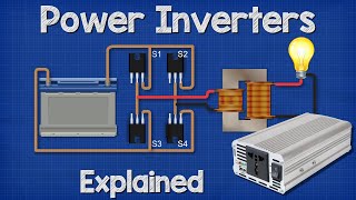
in the next segment we see that phase three is now approaching its positive peak so the current flows through this phase via diode five then flows through the load and then returns via diode four into phase one finally the current flows through phase 3 via diode 5 through the load and then back into phase 2 via diode 6. this cycle just repeats constantly like this the oscilloscope for the three-phase supply we'll see three sine waves for the ac electricity but the oscilloscope on the load will see this as a rough dc electricity with some ripples in it now we need to smooth out those ripples to clean up the dc electricity for this we connect a capacitor across the positive and the negative this capacitor is like a storage tank and will absorb electrons when there is excess and it will inject electrons when there is a reduction this will therefore smooth out the ripples in the dc electricity to a nice smooth signal on the oscilloscope we have covered capacitors in great detail previously do check that video out links down below now that we have clean dc we're ready to turn that back into precisely controlled ac at variable frequency and for that we need an inverter an inverter is basically a number of igbts which are switches that can turn on and off super fast i'm going to animate this using some simple switches instead of igbts just to make it easier to visualize i'll number these switches as follows to get our three phases we need to open and close switches in pairs to direct the flow of current from our supplier and a return pass that way the connected motor will experience alternating current remember ac is where the current reverses so if we took a lamp and connected it to some switches and a dc power source we can control the direction of current through the lamp by opening and closing switches in the right order therefore the lamp experiences alternating current even though it's coming from a dc supplier for the three-phase supply we time the switches to simulate the three phases let's see how this works first of all we close switches one and six this will give us phase one to phase two then we close which is one and two this will give us phase one to phase three then we close which is three and two this will give us phase two and phase three then we close switches three and four that will give us phase two and one then we close switches five and four and this will give us phase three and phase one and finally we close which is five and six and this will give us phase three and phase two this cycle repeats again and again like so if we check this with the oscilloscope we now have a pattern that looks like ac sine wave although it's just a little bit square this will work fine for some applications but not all so how can we improve this do you remember earlier in the video i said we can open and close the switch at different speeds and durations to change the waveform well we can do that with this too what we do is use a controller to rapidly open and close the switches multiple times per cycle in a pulsating pattern each pulse bearing in width this is known as pulse width modulation the cycle is broken up into multiple smaller segments each segment has a total amount of current that could flow but by rapidly pulsating the switches we control the amount of flow occurring per segment this will result in an average current per segment and we can see that this increases and decreases thus giving us a wave pattern the load therefore experiences a sine wave the more segments we have the closer it will mimic a sine wave we can control the output voltage by controlling how long the switches are closed for so we could for example output 240 volts or 120 volts just by trimming the opening and closing times we can control the frequency by controlling the timing of the switches so we could for example output 60 hertz 50 hertz or 30 hertz whatever is needed for the application remember by controlling the frequency we control the rotational speed of the motor so coming back to our vfd circuit we're going to use the controller to rapidly open and close the switches to vary the output frequency and voltage so by combining the rectifier the filter and the inverter we therefore get our variable frequency drive and this is what is used to control the speed of electrical motors and unlock energy savings in all sorts of systems okay guys that's it for this video but to continue your learning then check out one of the videos on screen now and i'll catch you there for the next lesson don't forget to follow us on facebook twitter instagram linkedin as well as the engineeringmindset.
Related Videos

11:08
Star Delta Starter Explained - Working Pri...
The Engineering Mindset
4,060,545 views
13:39
Power Inverters Explained - How do they wo...
The Engineering Mindset
3,707,263 views

8:35
Variable Frequency Drives Explained | VFD ...
RealPars
490,894 views

43:22
Lecture 1: Introduction to Power Electronics
MIT OpenCourseWare
667,645 views

21:06
How Power Transformers work ? | Epic 3D An...
The science works
295,287 views

7:30
What is the Difference between VFD and Sof...
RealPars
2,450,503 views

14:41
How 3 Phase Power works: why 3 phases?
The Engineering Mindset
1,334,307 views

20:14
How MOSFET Works - Ultimate guide, underst...
The Engineering Mindset
1,154,903 views
6:05
Understanding STAR-DELTA Starter !
Sabins Civil Engineering
7,817,281 views

20:39
Power factor explained | Active Reactive A...
Prof MAD
387,491 views
10:03
How does an Electric Motor work? (DC Motor)
Jared Owen
18,384,699 views

12:55
How to use a multimeter like a pro, the ul...
James Gatlin
2,249,169 views

11:30
How To: Troubleshoot VFDs
Radwell International
35,970 views
18:23
Why Circuit Breakers DON'T Protect People ...
The Engineering Mindset
1,364,694 views
16:33
Transformers Explained - How transformers ...
The Engineering Mindset
2,674,757 views

13:06
HUGE Magnet VS Copper Sphere - Defying Gra...
Robinson Foundry
53,822 views

13:38
How Variable Frequency Drives Work in HVAC...
MEP Academy
38,391 views

9:38
How To Convert DC to AC | Direct current I...
Prof MAD
1,261,074 views

25:33
Drive Basics
Yaskawa America - Drives & Motion Division
504,187 views

28:43
How to use a multimeter like a pro! The Ul...
The Engineering Mindset
2,166,428 views