What are Lead Lag Compensators? An Introduction.
406.55k views2069 WordsCopy TextShare

Brian Douglas
Get the map of control theory: https://www.redbubble.com/shop/ap/55089837
Download eBook on the fund...
Video Transcript:
welcome back to control system lectures this video is going to introduce the topic of phase lag and phase lead compensator x' now before I get started on this topic I want to really quickly explain the goal of these videos these control system lecture videos are designed to be a supplement to a normal control systems class or as a refresher to a practicing engineer I usually don't spend too much time working through problems or going over the math in great detail usually I'm spending most of my time explaining the concepts of what we're trying to learn
and then relating those topics to each other however recently I've been getting a lot of comments asking me to go through some examples in some of my videos so while this video is still just going to be an explanation video I'm going to try to follow it up with some examples in future videos so if you're looking for some problems worked out just know that they're going to be coming one day alright enough of that let's get to the topic at hand like we often do when we're talking about control systems we're going to start
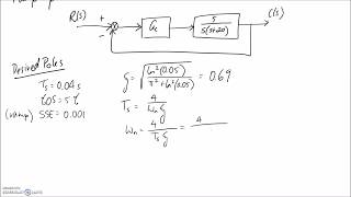
with a block diagram this is the block diagram for a typical feedback system and this block labeled controller is the transfer function that converts the error term into an actuator command and as the control system designer you're free to choose any control scheme you want for this controller block for example you can choose something like a PID controller or a lead or lag compensator or any other compensation technique that you want so that just begs the question now what is the difference between a compensator and a controller well I don't have a good answer for
that in my industry we tend to use the terms interchangeably however I've read a few sources that have differing views for example some say that the controller is the physical hardware or the computer and the compensator is the algorithm that you implement on the hardware I've also read the compensators are filters that compensate for deficiencies in a control loop by adding the exact same number of poles and zeros to a system where controllers compensate for deficiencies by adding different number of poles and zeros like in PID control where you add two zeros and one pole
I really don't like that second definition because I can't see how having a different number of poles and zeros could justify a new name but in any event I always like to learn something new so I'd like to hear your thoughts on the terms compensator versus controller in the comments below or in a video response but in this video I'm going to mean controller and compensator to be the same thing which is the algorithm that converts the error term into the actuator term but regardless of what you call it the transfer function that goes into
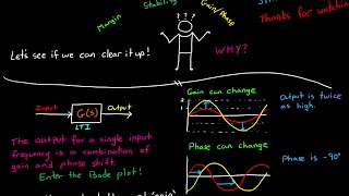
the controller block needs to be chosen in such a way that the closed loop performance of your system meets all of your requirements and phase lead and lag compensators are one of the tools that engineers use to accomplish this you can probably tell from the name that phase lead and phase lag compensator z' lead and lag phase but what does that mean exactly well let's look at phase lead if you start with a sine wave input and then you differentiate the signal we get a cosine wave signal out at the exact same frequency and then
if we plot both the input and the output on the same graph it's easy to see that the cosine signal is in front of the sine signal by 90 degrees another way of thinking of this is that the output leads the input by 90 degrees and we can plot the transfer function S on a bode plot you can see that the phase is positive 90 for all input signals check out my videos on sketching bode plots by hand if this isn't familiar to you alright so we can see now that differentiation gives you positive phase
and conversely integration would give you negative phase and that's because integration is 1 over s which is just the negative of differentiation on a bode plot so a zero in a transfer function adds phase and a pole in a transfer function subtracts phase but differentiation and integration alone don't make a phase lead and lag compensator however just like with a differentiator we've expect the lead compensator to add positive phase to the output for at least a certain range of input frequencies and we would expect the lag compensator to add negative phase to the output so
that the output lag behind the input to see if that statement holds up let's look at the equations for the transfer functions for a phase lead and phase lag compensator for a lead compensator the transfer function is made up of one real pole and one real zero and you'll see this transfer function written in a couple different forms but they're all identical to each other I prefer the form on the right since it's easier for me to tell what the roots are of the equation just by inspection you do have this extra gain at the
beginning here but that can be taken care of pretty easily if you're using the root locus method but the two things that make this a lead compensator is that there is a single pole and a single zero and also the zero is closer to the origin than the pole or Omega Z is smaller than Omega P now if I draw the equation for the transfer function for a lag compensator you're going to notice that they're remarkably similar in fact they're exactly the same if you draw them without numbers if you just use Omega Z and
Omega P and just like a lead compensator a lag compensator is made up of one pole and one zero however in this case the pole is closer to the origin than the zero okay let's plot a lead compensator on a bode plot and see what it looks like to do this I'm going to rewrite the transfer function as the product of a real zero times a real pole since I want to build a lead filter Omega Z has to be smaller than Omega P now the location of these poles and zeros can be anywhere on
the real line the only stipulation is that the zero has to be closer to the origin now we can sketch the approximate bode plot for each of these two transfer functions on the same plot so you can see what they look like in relation to each other the zero is going to add 90 degrees of phase and amplify high frequencies whereas the pole is going to subtract 90 degrees of phase and attenuate the high frequencies and when you multiply the two transfer functions together that's the same as adding the two lines in the bode plot
so our transfer function is going to behave like a real zero early on at the low frequencies and then get countered by the real pole at the higher frequencies so red lines are the approximate bode plots for our phase lead compensator one of the things to note about our phase lead compensator is that it increases the gain of high-frequency inputs but not as much as a zero would all on its own so this means that is going to be less noisy than a derivative controller on its own and the other thing is that you can
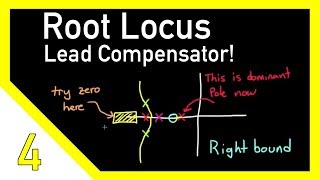
easily see that the lead compensator adds phase between the two corner frequencies and then adds no phase outside of this region and by adjusting the two corner frequencies or adjusting the locations of the pole and the zero you can move this positive phase region around let me show you what I mean by that with a quick example I'm going to start with a phase lead compensator and then show you how moving the zero around can morph it into a phase lag compensator let me first start by adding a real pole to our system and now
I'm going to add a real zero to our system closer to the origin so that makes this a phase lead compensator and the bode plot of each of these and the combined bode plot will look exactly like what we just did so there's no surprises there some amplification of high frequency signals and then some phase lead at the lower frequencies between the 0 and the pole but let me grab that zero and move it closer to our real pole it's still a phase lead system because our 0 is still closer to the origin and now
I'll redraw the zero on our bode plot you can see that it's a lot closer to Omega P and when we combine the two you'll see that the phase lead is a lot smaller than it was when they were further apart now let me grab the zero again and move it directly on top of the pole when weari plot the bode plot for that zero it's exactly the negative of the real pole so when you add them together they're going to exactly cancel each other out which makes sense because the pole on the zero would
just mathematically cancel each other out also so this is sort of a silly example now we'll take the zero and move it even further to the left and this becomes a phase lag system since the pole is now closer to the origin than the zero and when I redraw the bode plot for a real zero you'll see that it doesn't start to affect the system until a higher frequency than Omega P so that when I add them together the system starts to behave like a real pole at lower frequencies before being canceled out by the
real zero at a higher frequency and this adds phase lag to the system so hopefully this quick demonstration shows you how the exact same transfer function structure can produce either phase lead or phase lag just by adjusting the relative position of the pole and the zero so that covers the definition of the lag compensator or a lead compensator but what about a lead lag compensator well this is simply just designing a system that uses both a lead compensator and a lag compensator and we do this a lot of times in order to get the performance
that we need and I'll show you why that is in the next video when we actually start to design a lead lag compensator but in this example here you can see that this is made up of both a lag which is the red pole and zero and a lead which is the yellow pole and zero and the bode plot for something like that would look like this where it lags at low frequency then leads at high frequencies I'm sure this video only addressed a few of your questions and you probably have a lot of other
questions for example why do we even care about manipulating phase in a control system or why aren't we concerned with the change in gain in the bode plot or when would I use a lead lag compensator versus maybe a PID controller and how do I go about designing and tuning a lead lag compensator in the next few lectures videos I'm going to address those questions so stay tuned if you don't want to miss any of the future videos don't forget to subscribe and if you have any questions or comments please leave them in the section
below and I'll try my best to answer them now I'm starting to get more questions across all of my videos than I can handle so if you see that I haven't answered somebody's question and you know the answer please help me out and help out your fellow controls peers and provide the answer I'm sure they'd appreciate it that's it for now as always thanks for watching
Related Videos
13:58
Designing a Lead Compensator with Root Locus
Brian Douglas
484,543 views

11:42
What Is PID Control? | Understanding PID C...
MATLAB
1,861,329 views

15:44
What Is Feedforward Control? | Control Sys...
MATLAB
167,387 views
13:54
Gain and Phase Margins Explained!
Brian Douglas
661,905 views

7:44
PID Control - A brief introduction
Brian Douglas
1,522,716 views
28:48
Example: Design Lead-Lag Controller
The Ryder Project
99,337 views
29:55
Control Systems Tutorial: Sketch Nyquist P...
Aleksandar Haber PhD
30,617 views
16:40
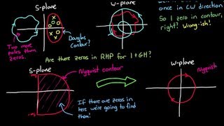
Nyquist Stability Criterion, Part 1
Brian Douglas
1,032,161 views

19:16
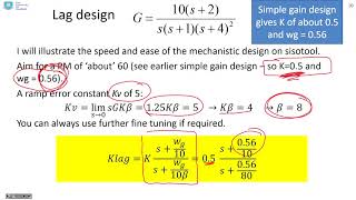
Lag Compensator
TutorialsPoint
166,059 views
49:18
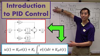
Introduction to PID Control
Christopher Lum
72,301 views
26:15
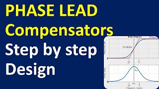
Tutorial on Step-by-Step Design of PHASE L...
Aleksandar Haber PhD
4,890 views
14:19
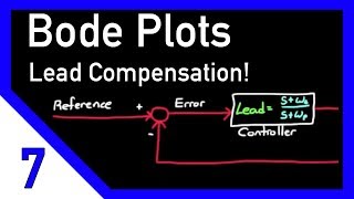
Designing a Lead Compensator with Bode Plot
Brian Douglas
367,972 views
23:55
Lead and lag compensation using Bode diagrams
John Rossiter
12,014 views
26:58
A real control system - how to start desig...
Brian Douglas
278,430 views
53:03
Root Locus Lead Compensator Design Example...
Joel Gegner
62,509 views

28:39
“Designed by Clowns!”| How Boeing’s Mistak...
Mentour Now!
747,063 views

24:10
This Is The World's First Geared CVT and I...
driving 4 answers
1,970,551 views
19:20
How to draw lag compensator using bode plot
Smart Engineer
54,706 views

16:04
Introduction to Root Locus
Christopher Lum
7,615 views