Inside the Horten Flying Wing
3.99M views2411 WordsCopy TextShare
Blue Paw Print
Become a shareholder in Blue Paw Print's parent company, Yarnhub.
https://www.picmiicrowdfunding.com...
Video Transcript:
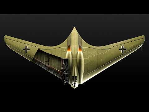
This is the Horten Ho 229 jet fighter/bomber. It was intended to be one of Germany’s super weapons in an attempt to turn the tide of the war with a fighter/ bomber that could reach a speed of 621 mph (1,000 km/h). With its futuristic appearance and wooden framework, the Horten was unlike any other plane from World War II.
But was it a real technological breakthrough for its time and was it stealth? We’ve modeled the Horten in minute detail inside and out to try and answer these questions. The Horten Ho 229 was developed in the late stages of World War II and was the first flying wing aircraft powered by jet engines.
There were 2 flying prototypes built. In this video, we will focus on the V3 prototype that was captured by the U. S.
Army in April 1945 and researched afterwards. My name is David Webb, and this is Blue Paw Print. Despite it’s futuristic shape, the airframe was quite rudimentary and extensively used wood in its construction.
The aircraft was 9 feet 2 inches (2. 81 meters) tall and 24 feet 6 inches (7. 47 meters) long.
The aircraft's wingspan was 55 feet 1 inch (16. 8 m), and the wing area was an incredible 557 square feet (51. 8 square meters).
The formidable flying wing design was intended to increase speed and significantly reduce drag. The fuselage was built from steel and wood, and the two engines that powered the Horten Ho 229 V3 were incorporated into the plane's main body. The skin covering the steel airframe was made from plywood, which formed the recognizable aerodynamic shape of the jet.
The aircraft's empty weight was just over 11,000 lb (5,067 kg), and its maximum weight was just under 20,000 lb (8,999 kg), which is about the same as a modern F-16, albeit without any weapons or fuel. The fuselage, wings, and landing gear were all built into a unified design. The aircraft’s plywood skin varied in thickness to obtain an aerodynamic shape.
The plywood was made of layers of thin veneer of European beech glued together, which formed a strong and lightweight design. It also had the advantage of using readily available materials. The plywood was attached to the metal airframe via wooden spacers.
Since the Horten Ho 229 V3 was mainly made of wood, it could swiftly catch on fire if sparks were present. This is why the plywood skin was painted with a fire-repellent green paint. The Ho 229 was one of the first planes to use the 'flying wing' concept, where the fuselage and wings formed a single structure.
Why did the Germans choose this design and what were it’s advantages? In short, it gave a greater lift and reduced drag, and gave better maneuverability. The plane's flying wing design was made from two delta-shaped, dihedral wings angled upwards at 4 degrees.
relative to the aircraft's horizontal axis. The dihedral wings gave the advantage of better aircraft stability during rolls. A secondary spar provided attachment points for the elevons - a control surface specific to the flying wing design.
The exterior of the wings was made of plywood boards. The almost tailless design of the aircraft did not include a vertical stabilizer, which increase the chances of sideslipping and, potentially, flat spins. The flying wing design without a vertical stabilizer wasn’t used for over 50 years after the war in an operational aircraft.
In part, this was due to the number and complexity of control surfaces that were needed to keep the plane stable. Elevons were positioned on the trailing edge towards the wingtips. They were used to control both pitch and roll instead of the more traditional setup of ailerons and an elevator.
When both elevons were in an upward position, the nose would pitch up, and when both elevons were in a downward position, the nose would pitch down. When the elevon on the right wing was up and the left was down, the plane would roll to the right, and vice versa. Each wing of the Horten had two flaps on the trailing edge.
These flaps were used during takeoff and landing and in other situations whenever the pilot needed to increase drag. Spoilers were another essential feature on the Horten. These were placed near the wingtips to create more drag and decrease lift.
A lifted spoiler disrupted the airflow above and below the aircraft, increasing the drag. Other spoilers were placed underneath the plane to the rear. Spoilers were critical in maintaining stability during landing and also at high speeds.
Next to the spoiler on the wing was a drag rudder. Drg rudders operated in pairs on the wing's upper and lower surfaces. When a drag rudder on one wing was used, it acted as a surface for yaw axis control.
When the drag rudders weren't being used, they were laid flat. With spoilers and drag rudders activated at the same time on both wings, drag was significantly increased. While ahead of it’s time, the many control surfaces and lack of computer control made the plane exceptionally difficult to fly, a problem that wouldn’t be solved for many years after the war had ended.
The Horten was powered by two Junkers 004B-2 Jumo engines, each with a thrust of 8. 9kN, or 2,000-pound force (lbf) at 8,700 rpm. The engine's length was 12 feet 8 inches (3.
86 m) with a diameter of 2 feet 8 inches (81 cm). The engine weight was 1,585 lb (719kg). Air was drawn into the open front section, then compressed by an 8-stage axial compressor, and fed into one of six combustion chambers.
In these chambers, the compressed air mixed with the injected fuel and, when ignited, it created a hot gas stream. Two engines could propel the plane to a speed of 607 mph (977 km/h). This came close to hitting the Luftwaffe’s design target of 620 mph (999 km/h).
But the aircraft's rapid pace came with a price. The engines were exceptionally fuel-hungry. The high-speed performance of the engines led the turbine to be prone to overheating.
By the end of the war, Germany couldn’t source high-quality alloys. This forced them to utilize lower-quality steel in the engine turbines, reducing the engine’s service life to approximately 20 hours of usage. The intake cowlings were made of metal panels and hammered to fit over the plywood material on the leading edge of the jet.
The exhaust panels were made from flat steel parts with a concave area. Metal panels protected the wooden structure of the plane. The fuel system consisted of eight aluminum tanks, four on each wing.
Two smaller tanks were positioned on the wing's leading edge and two more prominent ones on the central part of the wing. Their total capacity was nearly 528 gallons (2,000 liters), and fuel consumption was around 343 gallons per hour (1300 liters per hour). The fuel primarily used in the Junkers 004B engine was J-2.
This was a German WW2 synthetic fuel made from brown coal. It was pumped using the electric pump positioned next to the wing roots and the fuel tanks. The plane was designed to be armed with either 2 MK 103 or MK 108.
Both were 1. 181 inch (30 mm) caliber cannons and manufactured by Rheinmetall-Borsig. The MK 103 had a rate of fire of 380 rounds of high explosive projectiles and 420 armor-piercing rounds per minute.
The MK 108 packed a significant punch and was most likely to have been used against bombers. Unfortunately, we do not have any precise information on how much ammunition could have been stored, but when compared to a similar system on the Me 262, it was most likely to have been around 200 rounds for 2 cannons, in which case the ammunition would have been fed to the guns from a belt. Also, the Horten was designed to take two 1,100 lb (two 500 kg) bombs, albeit at the cost of increasing its overall weight, leading to changes in drag and required power.
Even though armament was in the design, the prototype that was captured and inspected by the Americans was unarmed, possibly because of war shortages or because it was in an incomplete stage of contruction. The Horten was a single-seat aircraft. The canopy was of a curved design and the canopy's curvature significantly increased the pilot's visibility and, without vertical stabilizers, gave the pilot a clear view of the rear of the plane.
The canopy consisted of two parts with the windscreen at the front and a rear section which slid back in order for the pilot to gain access. Directly in front of the pilot was a main panel upon which were switches for ignition, indicators for vertical speed, turn and bank indicators, airspeed indicator, and fuel warning lights. The second row of the panel housed indicators showing the flaps position, an altimeter, a compass, and two fuel indicators, one for the fuel tanks on the left wing and one for the fuel tanks on the right.
There was also a direction finder indicator which was an advanced piece of navigation equipment for the time, which picked up the direction of a radio beacon. Additionally, there were indicators for ambient temperature, engine RPM, and oxygen indicators showing pressure and flow. On each side of the control panel were two gauges for fuel injection pressure and exhaust temperature for each of the two engines.
In the upper left corner were indicators for the position of the nose gear and the side gears. Fuel tank switches were on the left of the pilot seat as well as a lever for deploying the brake parachute upon landing and a lever for controlling the spoilers. A flaps retraction lever and throttles were near at hand on the side console.
At the feet of the pilot were rudder pedals and toe brakes. On the right side of the pilot seat was a circuit breaker panel, a control panel for communications, and a canopy emergency handle. Also on the right was a lever for the ejection seat.
Using the manuals of similar German systems from the time, the following startup procedure would apply. The pilot would turn the battery switch to the ON position the inverter would be switched on, as well as the generators. He would check the throttles were at minimum.
He would then start priming the engine by pushing the priming button and simultaneously activating the tachometer. When the engines reached around 800 revolutions per minute, the pilot would activate the ignition switches. Once the engines reached around 1800 rpm, the pilot released the priming button and activated the fuel selector switches.
From then on, the fuel tanks would supply the engine. The pilot would push the throttle slowly. Before taxiing, he would lower the flaps.
As the plane moved forward the pilot would use toe brakes to steer the aircraft. Before take-off, the pilot would hold the brakes and push the throttles to maximum. After releasing the brakes, the aircraft would start down the runway.
When the speed reached around 93 mph (150 km/h), the pilot would pull the stick back, and the elevons on the wing would go into an upward position and the plane would lift into the air. The pilot would break the wheels to stop them spinning and then retract the landing gear. When the landing gear was fully retracted, hydraulically operated inner doors completely covered the wheels and gear, resulting in a very sleek aerodynamic profile.
The flying wing design made the wing load smaller than similar aircraft designs of the time, increasing lift and reducing stall speed. The plane was intended to take off from shorter runways, which was a significant advantage during the war due to Allied bombings of the German bases. It was estimated that the Horten V3 needed a runway of only around 3,600 ft (1,100 m) to take off.
The aircraft was estimated to achieve a cruise speed of 392. 7 mph (632 km/h). The estimated maximum speed of 607 mph (977 km/h), would make it faster than the American P-51D and the British Spitfire.
If the Horten Ho 229 had, in fact, entered active service, it would have proved to be a tough challenge for the Allies. The Horten was designed to withstand a force of 7Gs in a turn or a dive. However, research on the Horten estimated that the actual G force it could withstand was 12.
6 Gs. At that level, it would have almost been certainly fatal for the pilot. The Horten's landing speed was projected to be around 97 mph (156 km/h).
So that the plane was able to land on the same short runway it took off from, the plane was equipped with a drogue (drag) parachute that opened during landing to quickly lower the speed. The futuristic shape of the Horten started a number of rumors, and, in particular, the question was raised: Was it stealth? The aircraft's lack of sharp angles and sleek surface were thought to have decreased the radar signature.
Four decades after the war, Reimar Horten said he had also intended to add a charcoal surface to the Ho 229 to further increase its stealth capabilities. In 2008, National Geographic recreated the Horten in collaboration with the Northrop Grumman Corporation to test its radar signature. Soon after the documentary was made, Northrop Grumman published a research paper stating that the design was somewhat lacking in terms of stealth and that it could not be considered a "stealth plane" using the modern definition of the word.
Although the plane wasn't as stealthy as many have thought, its high maneuverability speed, and unusual aerodynamic shape made a unique example of military modernisation. For its technical solutions and projected specifications, it is considered that this jet fighter was well ahead of its time, but the end of World War II also marked the end of the Horten's development. Despite two successful flight tests on the second prototype (V2), the jet never saw combat.
The first successful operational combat-ready aircraft without vertical stabilisers was the B-2 Bomber, which was introduced over five decades later. The Horten Ho 229 V3 prototype is currently preserved at the Smithsonian Air and Space Museum. If you spotted any errors, please let us know in the comments.
We're looking to continuously improve. If you like this film, please check out our film on the B-17 bomber, one of the targets that the Horten was designed to attack.
Related Videos

21:59
The Evolution of The Rocket Engine
The Space Race
209,335 views
30:52
How a World War Two Submarine Works
Animagraffs
6,278,633 views

16:34
The Forgotten Prehistoric War That Killed ...
ExtinctZoo
2,497,875 views

25:04
The Insane Engineering of the F-35B
Real Engineering
8,993,799 views

11:58
When Spitfires Wing Tipped Cruise Missiles
Yarnhub
4,060,061 views

15:37
Men Fully Restore the BIGGEST GUN TANK IN ...
Quantum Tech HD
26,975,019 views
25:27
How an 18th Century Sailing Warship Works ...
Animagraffs
12,909,625 views

20:04
The Dumbest Drivers Ever
Daily Dose Of Internet
2,983,637 views

14:08
When a B-17 Tail Fell With a Gunner Inside
Yarnhub
13,037,448 views

12:06
How a Nighthawk Was Shot Down
Yarnhub
18,438,593 views
18:59
Real Stories From The Cockpit Of The Untou...
Not What You Think
2,129,424 views
18:37
How a P-51 Mustang Works
Animagraffs
8,824,067 views

17:30
The Airplane That Looked Fake, But Was 100...
Not What You Think
3,037,450 views
23:15
The First Jet Fighter. Heinkel 280 versus ...
DroneScapes
408,653 views

12:56
The Mysterious Plane That Made 127 Kills W...
Dark Skies
2,102,169 views

21:36
Why The UK Never Made Another Harrier Jet
The Military Show
1,141,425 views

30:03
Most Expensive Fails Ever Caught On Camera
#Mind Warehouse
196,873 views

17:26
New Ukrainian FRAGS Go Through Russian Tan...
The Military Show
1,648,213 views

22:46
Inside the Me-262 Jet Fighter
Blue Paw Print
1,438,080 views

8:17
MiGs vs Corsairs
Yarnhub
2,984,738 views