Introduction to D flip flop
2.2M views720 WordsCopy TextShare
Neso Academy
Digital Electronics: Introduction to D flip flop
Contribute: http://www.nesoacademy.org/donate
Sub...
Video Transcript:
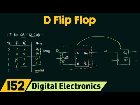
in this presentation we will understand what is D flip-flop and how we can make a deep flip-flop by using a SR flip-flop you already know what is SR flip-flop and I have made the truth table for SR flip-flop because this is the important thing from which we will derive the conclusion for our D flip-flop let's examine this truth table you can see if I want to store 0 then I have to give 0 1 and if I want to store 1 then I have to give 1 0 as the input my S will be 0
my R will be 1 then I have 0 stored in my SR flip-flop if my S is 1 R is 0 then I have 1 stored in my SR flip-flop now you can see a very interesting thing that this s and R are always complement to each other when s is 0 R is 1 and when s is 1 R is 0 so why we have to give this s and R individually we can just give one input to this flip-flop and complement the other that's what we have to do to get the D flip-flop
now you might be thinking that what about this case you can see this is an invalid case we are not going to use it so if you just want your data to be stored then you can have your D flip-flop where D is what deta and it is one of the most commonly used flip-flop because you just give your inputs store the data and remove the clock your data will be there so it is a very important flip-flop and JK flip-flop is the another most widely used flip-flop that we will see so what we have
to do to convert this SR flip-flop to D flip-flop is to let me extend this input I will take this input use a inverter and give the output of the inverter to R and this input I will call as D so now you can see that when D is 0 it means when s is 0 I will have R as one that was this case when DS 1 it means s is 1 and my R is 0 it means this case so I need only a single input that is my D and to get the
other I will complement it this is what we do to have our D flip-flop by using the SR flip-flop so I can make a diff lock like this in my D flip-flop there is a single input that I have called D and I'm having my clock of course and the two outputs Q n Q and complement and this thing this thing is what it is actually let me change the color for this if I hide this circuit and take my clock out so you can say that this circuit is inside this box now this is
how we will make a different flow it's time to move to the truth table for D flip-flop ok a very simple truth table you will have you will have your clock and a single input D ok an output QN plus 1 now when clock is 0 it means this circuit won't take any input and the output will be what the previous inputs of QN is my output in this case when clock is high and is low it means what s is 0 and R is 1 and for this particular case I'm having t1 plus 1
as 0 so this is 0 now when clock is high and D is 1 I will have my s as 1 and R equal to 0 it means this case and I'm having t1 plus 1 s1 and the other cases like as equal to 1 are equal to 1 is not possible in this D flip-flop because you can see a inverter a test here and simply we cannot have this configuration so this is the truth table for your D flip-flop a very simple truth table in the next presentation what we will have is the characteristic
table and the excitation table for the D flip-flop using this truth table so see you in the next presentation
Related Videos

4:10
Truth Table, Characteristic Table and Exci...
Neso Academy
1,254,568 views

7:46
Introduction to JK flip flop
Neso Academy
2,635,870 views

Meet Employees at Top Tech Companies in th...
Tech Jobs in 2 Minutes

12:27
Introduction to Multiplexers | MUX Basic
Neso Academy
2,732,489 views

8:23
Introduction to SR Flip Flop
Neso Academy
3,283,921 views

8:56
Truth Table, Characteristic Table and Exci...
Neso Academy
2,037,105 views

5:33
Difference between Latch and Flip Flop
Neso Academy
1,840,136 views

9:08
Master Slave JK Flip Flop
Neso Academy
1,668,840 views

23:56
Flight 5 Starship Return, Incredible Stars...
Marcus House
312,105 views
16:42
SR Latch | NOR and NAND SR Latch
Neso Academy
3,763,923 views

25:25
What's Outside The Universe?
Science Mirage
1,003 views

8:23
Under the End Caps - China AA Batteries - ...
KevReviews
233 views

8:25
Introduction to Sequential Circuits | Impo...
Neso Academy
2,684,663 views
6:58
5 Steps for Flip Flop Conversions | JK to ...
Neso Academy
1,205,704 views
14:28
HOW TRANSISTORS RUN CODE?
Core Dumped
433,377 views

9:55
James Webb Telescope Saw First Object Beyo...
Infinity Unveiled
2 views

18:53
The Rings of Earth // Servicing JWST at L2...
Fraser Cain
38,664 views

12:22
Designing a Sequence Detector Using D flip...
Foo So
3,174 views

8:58
Race Around Condition or Racing in JK Flip...
Neso Academy
1,338,359 views