Máquinas Síncronas (Aula 02) - Modos de Operação do Gerador
15.42k views3235 WordsCopy TextShare

LABMAQ
Máquinas Síncronas (Aula 02) - Modos de Operação do Gerador //
Este conteúdo foi produzido com o ob...
Video Transcript:
Hello everyone, today we are going to see the operating modes of synchronous generators. You have already seen that a synchronous machine can operate as a motor or as a generator. When it is used as a motor, we supply electrical energy and the synchronous machine converts electrical energy into mechanical energy.
When it operates like a generator in reverse, we supply it with mechanical energy and it converts mechanical energy into electrical energy. The agent that provides this mechanical energy, when we study synchronous machines, we call it the primary machine. This primary machine can be, in the case of a hydroelectric plant, a hydraulic turbine where the driving force is water.
If this is the case with a wind turbine then it is the wind moving the blades of the aero generator and so on until we get to combustion engines, diesel for example or electric engines is also a possibility although it doesn't make much sense for you to waste electricity to convert mechanical energy and then convert mechanical energy into electrical energy again with some exceptions. For example, what we have here is a specific generating unit for study. So we use an electric motor to move the generators.
For both the engine and the generator we have operating modes. For example , the engine can either function by providing mechanical power to me, mechanical energy, or as an absorption device or a supply of reactives, which is what we call a synchronous compensator, when the engine operates as a synchronous compensator. But we won't go into that now that the objective of today's video is to cover the generator's operating modes, in a future video we will deal with the synchronous compensator.
The generator will have several operating modes and for this we will use our generator testing laboratory, which consists of a primary machine, which is a direct current motor. A very old technology but it is very suitable for testing because it allows speed variation to be certain. Here we have a two-pole smooth pole synchronous generator.
And here we have an eight-pole salient pole generator. The axis of this machine is all interconnected with a magnetic clutch that makes it possible to disconnect the 8-pole machine from the system, let's say two-pole. Why?
What is the synchronous speed of the two-pole machine? It's 3,600 RPM and the 8-pole one will be 900 RPM. In other words, the 3,600 machine can rotate at 900 RPM, the 900 RPM machine cannot rotate at 3,600 for mechanical reasons.
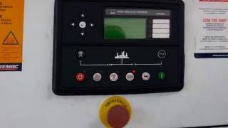
So we use the clutch to mechanically decouple that machine from this system. This is the command center that allows you to control both the primary machine and each of the generators. The generator can operate in two different situations: Online or offline.
What does this mean? When it operates online it is connected directly to the electrical grid. For example: a generator from Itaipu is injecting power directly into the country's electrical system, so it is connected directly to the electrical grid.
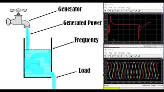
In the offline case, it is completely isolated from the electrical system, completely isolated from the grid. For example: Imagine that you have a country house in an absolutely remote place, very far away, where there is not even electricity. You have a waterfall and decide to create a micro generation for your own consumption.
Then you place a hydraulic turbine moving a synchronous generator and it generates energy to power your home. Do you remember the introductory classes? From the rotating field class?
The speed of my turbine shaft will dictate the frequency of the grid being generated. The intensity of the voltage, electrical tension in my network, will depend on the intensity of the field and also on the speed of my generator's shaft. The field could be made of permanent magnets, which would probably not be the case because if it were made of permanent magnets it would be fixed, so I would not be able to regulate it.
In this example, it would most likely be a machine with a coiled field, where I could increase or decrease the direct field current to increase or decrease the voltage level. So I put my turbine there, it's working, I regulated the speed to have a 60Hz source and I adjusted the field to have my nominal voltage there for my equipment. Then, I put a lighting system in my house, we put in a shower, I put in a refrigerator, for example.
When I connect this load to my internal network, there will be dynamics within the operation. What dynamic is this? When I connect a load to the system I am consuming power, energy, this energy is coming through the generator, electrical energy.
But the generator is just converting mechanical energy into electrical energy, so this mechanical energy is coming from my turbine and the water that is running inside. When not connecting the load, the dynamics are as follows: my turbine will find it more difficult to turn the shaft, that is, it needs to exert more power to turn the shaft. Because I'm demanding more power for my shower, my lamps or the refrigerator, this energy has to come from water.
If I don't increase the amount of water entering my turbine, it will lose speed and won't be able to rotate at the same speed because the resistance is greater. What happens in practice? This offline system, if I connect the load, the frequency will decrease and the voltage will decrease.
In fact, the voltage will decrease in two ways: when a current starts to circulate I will have a voltage drop at the terminals of my generator, due to the reactance of the machine and the losses in the conductors, and also because by reducing the speed I will also have a decrease in the tension level. Voltage is flow variation, so if I 'm decreasing the speed and I'm also decreasing the variation. And how do we fix this?
I connected a load, I have to go there and increase the amount of water that is entering the turbine and I have to increase field excitation to correct the voltage level. And this dynamic is constant. I turned on the shower, I corrected it, when I turn off the shower what will happen?
There will be energy left. There won't be any leftovers, right? But in fact I will have my turbine, which was encountering a resistance 'X', and suddenly this resistance disappeared to turn the generator shaft.
And when it disappears, what will happen? The machine will accelerate, it will fire, increase speed, and then my frequency, which was 60 Hertz, will rise to 70 to 80. I see that the system, when it is isolated, is very sensitive to variations, any variation in load dependent of a dynamic correction there so that the system continues to function well.
We will see how it works here in practice. [Music] Through the supervisory system, we have the operation data. The initial screen shows the generated power flow values, the rotation speed in RPM, and the field currents of the two 8- and 2-pole generators.
First we adjust the speed, accelerating the direct current machine to synchronous speed. Then we increase the field of the 8-pole generator until we reach the desired voltage. Which will be 220V.
To demonstrate these modes of operation, I prepared here three loads of approximately the same magnitude. One inductive, one resistive and one capacitive. So here we have the output of the generator, it goes to these two switches that will disconnect: Down here in position one, it turns on this bank of lamps, which are resistive loads, purely resistive, three-phase and balanced; And here in this switch, in stage 2, this capacitor bank will be connected, a load that is mostly capacitive.
There is always a little loss but almost everything is reactive/capacitive. And if I put it in stage 1, it will turn on this bank of inductors, which is also a mostly inductive load, apart from some small losses that it will have. So to begin with, let's see how the dynamics of the machine work when I insert a resistive load into it.
As expected, the active load slowed down the machine, which went to 867 RPM, hence the decrease in frequency and voltage. We also have voltage drop in the armature windings. So we have to correct the parameters by injecting more power into the primary machine, to adjust the speed, and then increase the generator's field current to adjust the voltage.
So it was at 0. 91 Ampere and went to 1. 01.
It's very subtle but you can also notice that now that we correct the voltage, the power that the generator is supplying ends up rising a little and also causes the frequency to drop a little more and then we have to give it another little touch to correct. When we remove the load, the primary machine speeds up and everything messes up again. Frequency went to 63Hz and voltage went to 250 volts.
So to correct it, we have to reduce the speed of the primary machine and then adjust the generator field. Now let's see what this dynamic looks like when I insert the reactive loads into the system. You will see that the behavior may seem a little intuitive.
When we place an active power load, that power has to be coming from the primary machine, when we turned on the lamps we had a loss of speed and it forced us to go there and correct it. When we place a reactive load, its behavior will be different, because the active portion of a capacitor bank or an inductor bank is very low. It only refers to the losses of capacitors or inductors.
But there is a phenomenon that happens in the synchronous machine, which causes it to work in a slightly particular way. We can say that inductive loads are demagnetizing for the machine, and capacitive loads are magnetizing for the machine. Very briefly: When a current circulates in the machine's armature, we have, inside it, in addition to the flux coming from the field, a flux coming from the armature.
And these flows interact with each other. When the load is purely inductive this interaction occurs in such a way as to cause: the resulting flux, the machine field, to be attenuated, severely attenuated. And when the load is purely capacitive, this flux is severely amplified.
It causes the fluxes to add up and then the flux of the machine's field is amplified. The result of this is: when we place an inductive load, the terminal voltage, which is directly related to the machine's field strength, drops very intensely, which is why we want to demagnetize. And when you add a capacitor, it's not a purely capacitive load, we have an increase in the machine's field.
So despite increasing the current I have a voltage drop, in the reactance of the machine, I end up having an increase in the terminal voltage. Because, in the end, the flow inside caused the machine's field to increase. Let's see how this works starting with capacitive loads.
The capacitor bank has minimal losses, and this 10 RPM decrease in speed was accentuated because attention rose to almost 350 V, thus the power more than doubled. In fact, here it is worth paying attention to the dangers of a sudden increase in voltage, as it could be enough to burn all the equipment connected to the system. To correct this we have to reduce the generator's field.
Now to reach the 220V terminal voltage, only half an amp of field is needed and not the 0. 9A that we had before. Frequency practically doesn't need to be corrected because it's just one or two RPM.
By removing the load suddenly, the magnetizing effect of the bench disappears. Now this 0. 5A field excitation is no longer enough to maintain the voltage, which is why it has dropped to less than half.
We often have to be a little careful not to be fooled by the meter, see that the speed actually increases a little, as expected. The frequency meter is measuring wrong, because it is outside the voltage scale, which is between 200 and 400 volts. To correct it, just return the field and 0.
9A. Finally, we will now only insert inductive loads. The demagnetization of the field causes a sudden drop in voltage that also leaves the frequency meter off scale.
Adjusting the generator field raised the current to 1. 2 A. Removing the demagnetizing agent, the voltage rises to almost 300 volts, which forces us, once again, to correct the field.
Well, you saw that this operational dynamic is quite boring, right? That's why these systems are always associated with some control mechanism and will be doing all this correction that we did here, it will be doing it automatically. Now let's see how this operates online, that is, connected to the network.
So our generator is no longer isolated and now it is connected to the electrical grid. We have to understand that the network is the result of thousands of sources (generators, electronic sources) all connected to the same point, so everyone is contributing to the network, the network will have a fixed frequency, so our network here in Brazil is 60 Hertz, and it will have a voltage level. Of course we have variations in voltage levels due to the transformers in the network, but wherever we connect our generator it will have a fixed voltage value and a fixed frequency value, that is, it is not possible to change the characteristics of the network when placing a generator connected to it.
It's what we call an infinite bus, we say that the network is an infinite bus, it's so big, so robust, that nothing that connects it to it can change its characteristics. The generator is a synchronous machine. So if the frequency is fixed and cannot change, it means that the speed in my generator is also fixed and cannot change.
So does this mean that: in the example of my water wheel, does this mean that even if I absurdly increase the amount of water going to the wheel, it will always rotate at the same speed? Exactly. What if I remove all the water?
It will also turn at the same speed. And the field? If I increase the field, will the voltage increase?
It's connected to the network, it's an infinite bus. The network is telling me the voltage here is 380V so I'm going to add more field and the voltage won't change. And in your decreasing the field, it also won't change the voltage.
We have to understand that the grid will be sovereign and my generator here is nothing close to it and will never be able to make any significant changes in these two parameters of voltage and frequency. So how does this thing work? When I increase the water flow in my water wheel, I am adding more mechanical power.
Power is torque times speed. We have already seen that the speed is fixed because the frequency is fixed, so what will increase is the torque. The torque on our turbine shaft will increase, providing active power to my generator.
And then my generator, which is connected to the grid, will inject active power into the grid to supply any load that is elsewhere connected to that grid. If by chance I want to change the machine's field, increase or decrease it, we will have control of the flow of reactants. And then the machine can operate in two different situations: it can operate under excited or over excited.
When it is operating over excited, it is supplying capacitive reactive to the network. It works like a large variable capacitor and I can vary this large capacitor by changing (increasing or decreasing, in the case of a capacitor it is over excited so it would have to increase) the field in the machine to correct some power factor or even make the correction and control of the flow of reactives in the transmission line. In the same way it can operate sub-excited.
Operating under excited, that is, the field is reduced and it works as a large inductor, a variable inductor. This is very important, very relevant, because the entire control system and reactive flow of the transmission lines are controlled, the vast majority of which are controlled in the generation plants themselves by synchronous generators. So let's fire this guy up and see how he operates under these conditions.
[Music] Connecting the generator to the grid is not a trivial process. Firstly, we have to adjust the generating unit to the network conditions at the point where the systems will be interconnected, in this case, 380V line at 60Hz. Next we need to synchronize the generator with the grid.
To do this, we use a digital synchronoscope that guides, through LEDs, the delay or advance of the system to close the circuit only when everything is in phase. [Music] Once the system is online, voltages and frequencies are stable. The supervisory system shows the power flow, which, at the time of synchronization, must be practically zero.
The speed, as we saw, is stabilized at 900 RPM with the values varying only within the sampling range that comes from the tachometer. We have increased the power of the primary machine. Now the generator starts to inject almost 6kW into the network, despite the terminal voltage not changing, the voltage drop in the reactance and internal resistances of the generator continues to exist, therefore, when we change the operating point, injecting active power, the voltage drop internal puts the machine in an under excited condition and that is why the network is supplying these 1700 VAR, that is, the generator is also operating as an inductor.
Be careful not to get confused with this negative sign in reactive power. Normally we measure a charge, which when it is capacitive has a negative Q (-Q) and, when inductive the Q is positive (+Q), but here the inductor or capacitor is on the source side, and then the signal has to be inverted. Well, to correct this under-excitation condition we have to increase the generator field.
It was 1. 61A and went to 1. 82A, and now we are just supplying active power to the grid.
If I reduce the power of the primary machine too much, our generator starts to operate like an engine using energy from the grid to maintain speed, but this is far from being a desirable mode of operation. Well, if we want to supply capacitive reactive to the system, we have to operate with an over-excited machine, increasing the field current. We are now supplying 6,300 VAR and the field at 2.
44A. When we decrease the field and operate in the under excited condition, the flow of reactants reverses and now we have the equivalent of a large reactor. The moment the grid and generator are disconnected, the machine returns to offline mode where the voltage and frequency are no longer fixed.
So guys, these were the operating modes of synchronous generators. Happy studying and see you in the next video. It cost.
Related Videos

30:42
Máquinas síncronas (Aula 01)
LABMAQ
28,124 views

23:59
Transformadores (Aula 02) - Núcleos
LABMAQ
40,669 views
7:35
Droop Characteristic/Droop Control of Sync...
A Serious Circuit
43,984 views
10:17
The Difference between electrical MOTORS a...
Engenharia Detalhada
49,800 views

14:30
Funcionamento Gerador síncrono excitação b...
Eng. Luís César Emanuelli
15,091 views

11:17
Conversão de gerador para compensador sínc...
Elétrica sem Limites
4,714 views

30:55
Motores de Indução (Aula 04) - Motores ...
LABMAQ
14,326 views

10:55
What is BRUSHLESS ENGINE? Unlocking the Po...
Engenharia Detalhada
348,604 views

13:15
Partida e sincronismo do gerador hidrelétrico
Elétrica sem Limites
10,053 views
8:59
21Setembro2016. Manutenção em Geradores - ...
D Elétrica - Manutenção em Geradores
99,787 views
16:46
Curva V do Gerador Síncrono
Eng. Luís César Emanuelli
9,161 views

11:45
Motores de Indução (Aula 01) - Introdução
LABMAQ
70,060 views

15:02
Como funciona um Motor de Navio (Praça de ...
Eu, digo, Rodrigo
261,544 views
13:50
Campo Girante de Máquinas Elétricas
LABMAQ
10,750 views

22:50
Ensaio em Vazio, Ensaio de Curto Circuito ...
Campo Girante
4,857 views

6:38
Como testar gerador de energia
Manutenção Predial - Felipe Lima
6,120 views

14:25
Como funciona um aerogerador de parque eól...
Escola Eólica
17,271 views
20:12
Como conectar um GERADOR SÍNCRONO em paral...
Campo Girante
7,553 views

12:44
Motores de Indução (Aula 03) - Ensaios n...
LABMAQ
14,771 views

14:17
COMO LIGAR UMA PLACA RETIFICADORA DE UM GE...
CENTRAL DOS MOTORES
2,936 views