Bombas Centrífugas - Conceitos Básicos
28.34k views3453 WordsCopy TextShare

Bombas Centrífugas & Cia.
Nesse vídeo, abordarei de maneira simples e resumidamente, alguns conceitos básicos e fundamentais p...
Video Transcript:
[Music] Hello everyone, welcome to another video from the "Minutos de Saber" channel, bringing important information about centrifugal pumps. In this video, I will cover some basic concepts related to this equipment. I kindly ask you to subscribe to the channel, as it is crucial for its continued growth.
Don't forget to turn on notifications, so you will be informed of each new video I post. If you like it, leave your like and thumbs up. Questions, criticisms, suggestions and comments are always welcome, right?
So, let's go to the video. Before starting, I want to make clear the topics that will be covered. I will talk about the pump set , the energies involved in pumping, some components of a centrifugal pump, types and rotors, the basic operation, the direction of rotation of the rotor (which is crucial), flow rate and head .
These are fundamental parameters for those who work with centrifugal pumps, as well as the concepts of NPSH and cavitation. These are simple themes, but essential in my opinion, for everyone who deals with this type of equipment. Some of these topics have already been detailed in previous videos on the channel.
Therefore, I invite anyone interested in deepening their knowledge to watch the specific videos on types of rotors, flow and head, NPSH, cavitation and components. I hope you enjoy! ** Okay, everyone.
Before we start, it's a very basic video, as the title suggests. If you want to delve a little deeper, I have several videos detailing this subject. It's true?
So, let's go. Hope you like it. Okay, let's get to work.
So, the pump set consists of the engine and the pump. The pump in this case is, of course, a centrifugal pump. The engine can be electric, internal combustion or a turbine.
Generally, we deal with electric motors, which are the most common. OK, there we have a coupling. What does this coupling do?
Transmits torque, movement from the motor shaft to the pump shaft. OK, we have the suction flange, or pump inlet, outlet flange, or pump discharge, and the base. The base, obviously, is not part of the pump, but it is a part, a fundamental component for this entire set to be assembled.
OK? What are the components of a centrifugal pump? I'll go ahead, I'll leave some links in the video description, because I have several videos detailing various subjects.
So, I ask you to kindly, anyone who is curious, wants to find out a little more, watch the videos on the channel, it will be very easy to understand. OK? So, we have the casing, the pump body, spiral body, there are several names; the rotor, also called the impeller, is generally the most used term; the pump shaft; the bearing box or bearing housing; the stuffing box, and inside that stuffing box, I have my seal, which could be gaskets, it could be a seal made by mechanical seals.
There are other fences, but, as I just told you, let's stick to the basics. And there is a lid, in this case, this bomb has a lid. OK, so basically, obviously, guys, there are a lot more components, with a lot more information about each component.
But, as I'm very basic, let's put it this way, for those just starting out in the subject, that would be very basic. What are the energies involved in pumping? So, in this case, we have the electric motor, where the electric motor receives electrical energy and transforms this electrical energy into mechanical energy.
This mechanical energy is supplied to the rotor through a shaft. So, here we have the pump shaft, the motor shaft, and that coupling that we saw. That is, this rotor is powered by mechanical energy.
So what does the bomb do? The pump transforms this mechanical energy into hydraulic energy. Ah, Marcos, and how does this transformation happen?
That's what we're going to see. So, there is already suction and repression. Sometimes there is confusion.
Suction, repression, okay. Generally, in the vast majority of cases, the diameter at suction is larger than at repression. It's true?
So, guys, I'm going to explain how the bomb works. Look at the spiral body of the pump. Why is it called a spiral body?
Because it has a spiral back. Some bodies have two, but that's not the point, like I said, let's stick to the basics. Note that, towards the pump discharge (outlet), the internal area gradually increases until the exit.
So, if I stretch this here, imagine that I cut here and I'm going to stretch this body. If I stretch this body, it will look like this, from a small area to the discharge, which is a larger area. Note that, with the increase in area, there is a decrease in fluid velocity and, consequently, an increase in pressure.
That's energy conservation, folks, based on a physical principle. Here I represented some pressure gauges. As the fluid moves to a larger area, the speed decreases and the pressure gradually increases.
OK, it's a basic principle of hydraulics and it's how the pump works. Note that the rotor also, between the rotor blades, the area gradually increases. Then, the area between the rotor blades also gradually increases towards the casing.
Remember the carcass is here. Towards the carcass, this area gradually increases. What is the direction of rotation of a rotor?
This is a very common question, but for those who work with bombs, this is not a question. The direction of rotation of the rotor is that in which the fluid moves from a smaller area to a larger area. The fluid enters through the eye of the rotor, through the center of the rotor, and is driven by centrifugal force, which is the principle of centrifugation.
Centrifugation is a leak from the center, the fluid is expelled from the center to the periphery, to the edge of the rotor. Right? So, this is the correct direction of rotation.
If the direction is the opposite, the fluid will be wrong, because the tendency is to come from a larger area to a smaller area, and that is not what we want. Therefore, this direction of rotation is wrong, incorrect. OK?
Continuing, now I have the impeller spinning correctly, the vanes are curved back like this, they push the fluid towards the casing, the pump body. The fluid is pushed radially in all directions to the end of the rotor. Therefore, the fluid is being pushed radially toward the end of the rotor.
Pedro, there is a significant increase in velocity as the fluid reaches the edge. The further the fluid is from the center, the greater the speed. Okay, so when the fluid reaches the end of the rotor, it is at very high speed.
Low pressure is created in the eye of the rotor. Remember in the videos I've already posted, I always say that the pump works due to a difference in pressure. As the fluid is being centrifuged, being expelled from the center to the outside, what will happen, folks, is a drop in pressure, a decrease in pressure.
And as the centrifugal pump pumps due to a pressure difference, in the case of an open reservoir, for example, the atmospheric pressure is greater than the pressure in the eye of the rotor. The higher pressure pushes the fluid toward the eye in the center of the rotor. Okay, moving on.
What's going to happen now, guys, when the fluid leaves the rotor at very high speed? It will hit the casing, it will hit the pump body. Then, the high-speed fluid flows and reaches the pump body.
Most of this kinetic energy will be transformed into potential energy, that is, pressure energy. Again, energy conservation, okay? More fluid continues to enter, and a continuous flow is generated.
Remember low pressure? In the same way that I am expelling, throwing this fluid out, it continues to enter. What's coming in?
More liquid here in the rotor eye, right? As the internal diameter of the casing increases, what's going to happen, guys? It will slow down.
If you reduce the speed, what will happen to the pressure? Increase the pressure. So, look what I did here to make it really clear, guys.
I imagined that I drilled this housing and put several pressure gauges in it. Here, six pressure gauges along the entire length of the body shell. You can see that the pressure gradually increases towards the discharge.
Remember, both in the rotor, the area is coming from a fluid coming from a smaller area to a larger area, and in the casing, also, from a smaller area to a larger area. Okay, so I'm transforming velocity energy into potential energy or pressure energy. Okay, basically, this is how the centrifugal pump works.
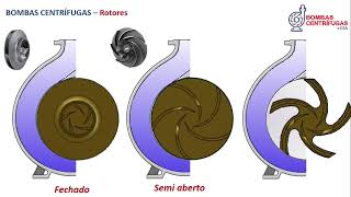
It can have some types of rotors. Once again, guys, I have videos on the channel talking about the type of rotor depending on the fluid pumped, type of rotor depending on the fluid passing through the rotor. Then, I'll leave it in the video description.
I'm sorry, here I have closed type rotors. I have semi-open type rotors, I have open type rotors. Note, once again, that the rotor is always rotating in the direction in which the fluid moves from a smaller area to a larger area, both in the rotor and in the pump casing body.
Okay, so this is the open rotor. Marcos, but when the closed rotor is used? Once again, guys, we have videos on the channel detailing this, ok?
So what will happen when the pump is in full operation? Remember, I'm causing low pressure in the eye of the rotor. So, what will exist?
A suction. The fluid goes to the eye of the rotor, it will gain energy in this component, which is the rotor. This energy will be transformed into pressure energy or potential energy.
And when flushing, where am I going to pump it, guys? As irrigation, for a water tank, for a heat exchanger, for a cooling tower, for a boiler, in short, I will do my pumping there. Right?
The centrifugal pump has several parameters, but two are the main ones: the flow rate, indicated by the letter q, and the head, indicated by the letter H. Normally, we call this term pressure. Okay, the flow, guys, is influenced by the width of the rotor, the width of the passage in the motor.
If you take the manufacturer's manual, the rotor passage will be there in the technical data, this measurement here, obviously. This is very easy to understand. The larger the rotor passage, the greater its width, consequently, the greater the flow.
This is very clear, very obvious, right? See that here I put the diameter equal. Imagine the same rotation, but where I have the larger width, what's going to happen, guys?
The flow rate will consequently be greater. I can vary both the flow rate and the head or pressure if I vary the rotation. I also think that, because this figure looks like an animation, it's very clear, right?
A lower rotation and a higher rotation, where I have a higher rotation, consequently, I will have a variation in flow and depression. So, if we put this on a graph, this here, guys, we call it the pump's characteristic curve. In the future, I will detail the curve, types of curve and how we draw the curve, but for now, going back to the basics, the pump curve shows the pressure and flow.
Every time I change one, it will affect the other and vice versa. So, I can vary both the flow rate and the head or pressure if I vary the rotation, right, guys? So, imagine there, I have the characteristic curve of this engine for this speed, where I have a flow rate and a pressure.
Ok, if I reduce this rotation, guys, let's suppose I reduce it by half, what will happen, guys? I will have another curve, where I will have another flow, of course, a lower flow and a lower pressure. There is a law here, folks, that governs this, called the laws of similarity.
There's no point going into that detail now, but there's a whole relationship there, right? And I also have the possibility of changing the flow rate and head, which is often used by varying, oops, sorry, the diameter of the rotor. I think it's also very clear, right, guys, when we vary the diameter of the rotor, it will automatically affect the flow rate and the head.
So, there you have it, a motor with a certain speed, a certain diameter, I have the curve, where I have, repeating the previous data, flow and pressure. Okay, look, same rotation, just with a smaller rotor. What will happen, people, due to the similarity?
I have a flow drop, I have a pressure drop. Ok, so, two very common ways to change what we call the pump's working point. The pump has a great advantage, being centrifugal, the same equipment works at dozens, hundreds of operating points.
It's not a fixed point, I can vary it. So, in what way? By varying the rotation, yes, with a speed reduction box, through the frequency inverter.
I can do return machining, so there are an infinite number of ways, the infinite, no, there are some ways that we can change the point of operation of a pump. Continuing, guys, another very interesting parameter, another very important piece of information, is called NPSH. This scares a lot of people, but it's not scary at all.
NPSH stands for Net Positive Suction Head. So, whoever is interested, take a look there, okay? But, once again, it's just the basics, okay?
The NPSH we have two phases, the NPSH available, which is part of the installation that you have in your company, in your home, right? So this installation will give me an NPSH, called available. It's true?
And I have to compare my available NPSH with my required NPSH, which is part of the pump. What do you mean, guys? This is bomb.
Who should provide this information to you? The manufacturer, okay? The manufacturer places this pump on test benches, performs the test, makes the pump cavitate and determines the required NPSH.
We have the pressure, okay? Pressure available at the pump suction flange. OK?
The installation gives me an available pressure. It pursues the required pressure that the pump needs so that there is no cavitation. So, as I told you, the required NPSH is a manufacturer's characteristic.
The manufacturer provides this information in the manuals and technical manuals. Don't worry about this information, you don't need to calculate it, the manufacturer shows it to you, okay? Depending on the flow rate, I will have a necessary pressure at the pump inlet.
OK? The NPSH available, yes, you have to worry. With what is available, the pressure at which the fluid will reach the suction, guys, will depend on who?
It will depend on the type of installation, whether it is suction above the pump, whether it is below the pump, it will depend on the levels, whether it is higher or lower. If the suction is negative, that suction below the pump, right? The further away from the pump, the worse, pressure loss in my piping, if I have a lot of piping, a lot of pressure loss, a lot of accessories, it will influence the pressure at the pump inlet.
Fluid temperature, the higher the temperature, the greater the probability of what happens, that we vaporize the fluid. And vaporization causes cavitation. Installation altitude, right?
If you have a pump installed at sea level, you have a good condition. If you have an installation at an altitude of a thousand meters, it is a little worse, because the atmospheric pressure decreases as the altitude increases. Vapor pressure , right?
It is completely linked to temperature, the higher the temperature, you will have different vapor pressures. And other information, okay, guys? So, once again, I have a video on the channel that talks a lot about this, okay?
What is the condition for there to be no cavitation, guys? You will compare your available pressure, that is, the pressure that the installation provides to the pump, with what the pump needs. What is the condition then?
The available NPSH has to be greater than the required NPSH, greater, at least equal, because when we read the required NPSH, we add another half meter, you know, one meter. So, greater than or equal. Ah, but when it stays the same, guys, it's very close to cavitation happening, okay?
But then, firstly, what does the available NPSH have to be? Bigger, that is, what I'm saying is that the pressure that the installation gives to the pump has to be greater than the pressure that the pump needs in its suction, so that there is no what? Cavitation, people.
Ah, what is cavitation? It comes from a cavity, oh, but it remains a cavity, that cavity that the fluid, the vapor pellet, leaves in the engine. No, people.
When fluid turns to vapor, what happens? A cavity there, and cavitation comes from precisely that name, okay? I have a lot of information about it in the video, on the channel .
Suction, discharge, rotor eye, rotor inlet, I'm having flow, having pumping, okay? What will happen, guys, with the pressure? Cavitation happens when the pressure in the eye of the rotor drops, the pressure of the pumped fluid becomes lower than the pressure at which the fluid vaporizes, okay?
So, suction pressure, imagine here, suction, rotor eye and discharge. Suction, eye and discharge, vapor pressure, what's going to happen there, guys? It will vaporize, it will not vaporize, why?
Because the suction pressure is greater than the vapor pressure, okay? That's it, folks. So once again, I have there There's a video on the channel talking a lot about this.
The pressure inside was dropping, dropping, dropping, but it didn't reach vapor pressure, so no bubbles were formed, steam bubbles, okay? It's not an air bubble, no, it's a vapor bubble, people. If steam bubbles don't form, cavitation will happen, right?
So, one more warning, guys, cavitation, NPSH only in suction. Ah, Marcos, but why? Because in repression, we already have high blood pressure.
If we have high pressure, we do not have low pressure, if we do not have low pressure, but we do not have cavitation, we do not have the formation of vapor bubbles. And look at this case here now, folks, it's really a scam, okay? Just look what will happen.
Now, notice that the fluid came, came, the pressure dropped a lot here, remember, the pump works due to a difference in pressure, so the pressure decreases as a result of friction. The fluid is moving forward, the pressure is falling, falling, falling, falling, it has reached vapor pressure, people. What will happen?
Formation of steam bubbles. If a steam bubble happens, cavitation will happen, okay? And what is cavitation?
Very simple, watch my video on the channel that talks a lot about cavitation. The fluid is heading towards the pump suction, there comes a point where the pressure reaches vapor pressure, usually very close to the eye, I drew it here to make it clearer, bubbles begin to form, what are these bubbles? No, vapor bubble, I talked about the vaporizer, okay?
The fluid goes into the pump, inside the rotor, the pressure increases suddenly, okay, because the rotor is supplying energy, that vapor bubble condenses, starts to hit, they start constant bombardment here in the rotor, in the internal parts here, and It turns out that we have cavitation. So, cavitation is the cavity that the vapor bubble caused there in the flow, here in this column, it is not the cavity that the bubbles cause, right, in the implosion of the bubbles they cause in the rotor. Okay, so here, guys, okay.
Why do these bubbles happen? Because the brake pressure was lower than the vapor pressure, right? So, guys, that's it.
I hope you liked it, very simple, very quick explanation, I didn't go into details, right, check out my videos there, they have a lot of interesting information, guys. Once again, subscribe to the channel, it's very important, okay, turn on the notifications. And if you liked it, leave your like, comments, criticisms, suggestions, feel free, people.
It cost! A big hug and see you in the next video.
Related Videos

19:33
Bomba Centrífuga x Bomba Periférica Qual ...
Bombas Centrífugas & Cia.
20,931 views
29:20
Bombas Centrífugas Conceitos Básicos 1
Bombas Centrífugas & Cia.
1,707 views

16:30
Tipos de Rotores Utilizados em Bombas Cent...
Bombas Centrífugas & Cia.
11,485 views

7:24
Bomba deslocamento positivo e não positivo
idoffshoread
33,167 views

11:14
Entenda o fenômeno da cavitação em bombas ...
TRACTIAN
13,814 views

6:31
Válvula de Retenção Pilotada
Prof.:Elias Faustino - Cursos Online em Animação
34,625 views

19:58
Everything About Irrigation Pivots (Farmer...
SmarterEveryDay
5,379,501 views

8:26
Centrifugal Pumps
Laney Machine Tech
1,103,192 views

4:48
Como funcionam as Bombas submersas?
Lesics português
639,398 views

10:53
NPSH requerido e disponível: como calcular
Bloom Consultoria
93,753 views
7:49
Bombas Centrífugas: Entenda o funcionament...
TRACTIAN
25,893 views

30:57
Bombas Centrífugas e seus Principais Comp...
Bombas Centrífugas & Cia.
29,946 views

20:22
Escorva de Bombas Centrífugas - Como fazer?
Bombas Centrífugas & Cia.
10,729 views
6:22
BOMBA DE ENGRENAGEM - Como Funciona
Oficina Agro
64,987 views

8:38
Bomba Afogada e Bomba Não Afogada | Dimens...
Engenharia e Cia
9,902 views
9:48
Solenoid valves | The Beauty of Engineering
Lesics
1,003,330 views

31:18
Bombas Centrífugas Multiestágios
Bombas Centrífugas & Cia.
5,035 views

19:06
Why Harmonic Drives Are Awesome.
Jeremy Fielding
185,916 views

13:30
Manutenção Bomba centrífuga colocação de s...
Ventura Manutenção Industrial
36,900 views

1:08:56
DIY Rocket Engines - Easy and Cheap!
Tech Ingredients
2,807,542 views