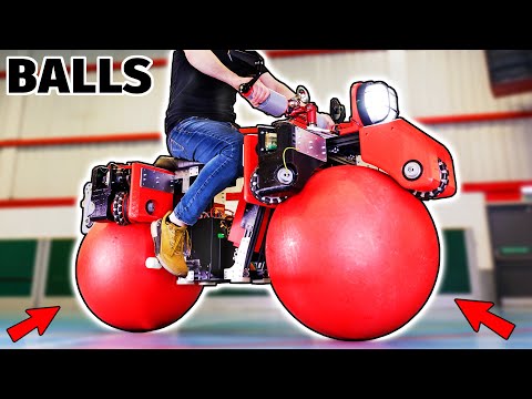
I built an Omni-Directional Ball-Wheeled Bike
4.87M views4853 WordsCopy TextShare
James Bruton
Ad: Use code: PCBWay-James Bruton to get $10 off orders of over $30 at PCBWay. Go to: https://www.pc...
Video Transcript:
[Music] yes it's time to make another omnidirectional bike the three previous ones featured one Omni wheel on a bicycle two Omni Wheels which balance sideways and then it had to be blown along with fans and then I tried four mechanim wheels so the bike can move in any direction but also screw itself along forwards and backwards and of course you can check all of those out in my channel this time though I I'm going to try and make a bike which balances on two balls which can roll in any direction these are rigid balls called Walking Globes and they're used by circus ax to balance on and this is the sort of thing you can buy in juggling shops these are totally rigid and include a stopper for filling them with sand to slow them down but I'll be leaving them totally Hollow they really are really round so they roll really well I'm going to use three Omni Wheels to drive each ball which have little wheels all around them so they can slide sideways I previously made a ball balancing robot like this which worked okay but I had issues at High Velocity cuz the wheels seem to fight each other this time I'm going to turn the wheels around 90° which should allow the ball to roll faster but I'm only going to power two of the wheels and leave the third as an idler so it's really important that the bike can balance sideways and balance sideways like a segue or hoverboard to stay upright because otherwise it's going to be impossible to drive so we've got the wheels at this orientation where we've got them 120° apart and that's so we can drive sideways and we can also Drve forwards and backwards by spinning those Wheels in opposite directions to get linear travel this way however with the wheels like that and the Omni Wheels having the little wheels I'm not sure if there's going to be like weird slippage and we won't get linear velocity between the wheel velocity and the ball and whether the ball will just like spin around instead of going sideways in a weird way cuz all those little wheels will allow it to actually freely rotate if that happens then we're going to have to Miz the Third Wheel which is planned to be an idler but that one will then need to turn round 90° so it has some effect to actually drive it sideways anyway I'm about 90% sure it'll work like this but I've never built a ball balancing robot with the wheels in that orientation so I think all we can really do is go and build it and find out if it works so it's time to 3D print some parts there's quite a lot of large chunky parts to print for this so thanks to my 3D printing sponsor which is LSB 3D printers I'm using the 1. 2 mm nozzle to make lots of these parts so you can see how fat those extrusions are how fat the infill is and how big those parts are and there's several of those to support all of those Omni Wheels 120° apart this one has support material in to put in some 4040 Extrusion but on the whole there's huge chunky Parts going to make up the structure there's also some parts printed with a thinner nozzle and those to allow tolerancing so that we can insert them in the fatter parts and use them to hold bearings and so on thanks to 3D fuel for the filament for for this project you can now get 10% off at 3D fuel. com with my special code and Link and I'll get a small commission we're going to be using o drives for this project which was the same on the screw bike these are 8325 Motors and they have a magnet on the back so that we can put the O Drve S1 driver sandwiched on the back and it can control position velocity or Torque these come in a kit with all the mounting plates and we've got four of those in total so we've got one of those to drive each of the four driven Wheels out of six each motor is mounted on a 3D printed plate and that plate is attached to one of the big chunks made with a 1.
2 mm nozzle so that fits neatly in there so I can get to the connectors thanks to Simply bearings for the bearings for this project there are lots of bearings in the wheels and in the idlers and everywhere else so this thing comes in two sides we've got those pieces I made with a finer nozzle that we can insert those bearings in the bearings are pushed in either end and then those black things are going to get inserted into the chunky prints and you can see that that's really well toleranced so those get glued in and that means I only have to reprint that part should the tolerancing be bad rather than the whole thing so here are Omni wheel assemblies these come in two halves with a spacer in between and that is fitted onto a square axle made of 2020 Extrusion with a pulley on one side and a spacer on the other which basically connects to the 2020 and holds everything firm and of course those roll in One Direction and slide in the other we've got two Dy belts in our gearbox and an intermediate pulley this is essentially a converter from a T5 to an hd8 and this is actually not much of a reduction but it's the same reduction that we had in the screw bike and so taking into account the ball diameter we should get the same velocity on the wheel so obviously that intermediate gear sits in between the motor and the wheel itself and it offers some reduction but not much so we now have the other half to insert which has bearings a little stud that goes in the motor to hold it and a hole for that pulley so that everything is tensioned and everything stays tight here is one assembled unit so we should find that we've got that intermediate pulley the wheel the motor and all of those belts are tensioned and everything is double braced at both ends of the axle so that's nicely back drivable and everything moves smoothly and on the other side we've got this curved cutout which is where the ball is going to sit and that wheel of course is going to rest on the ball to drive it there are four of these that I've had to assemble for our four driven units to drive our two balls so those are looking pretty good and I did remember to make mirrored pairs of course these are looking pretty good and my belts are actually pretty tight on all of these I have left provision to put an idler in on each of the belts if I want to tighten the belts up if they stretch but basically just the spacing looks perfect at the moment and hopefully if I've worked this out right then we should have the same reduction onto these wheels taking into account the ball that we did have with the screw bike so we should have enough power but I'm just going to power one of these up and see how torky it is the O Drve tool allows me to run this and monitor the veloc the current and the position of each of the motors just going to do five Revolutions a second on the motor and then we've got this reduction which isn't very much but ow God that's pretty tough actually that's all right let's just try try a bit more that's about 11 Revolutions a seconds I definitely I definitely can't stop that and it'll go the way up to about between 60 and 80 so we should have enough velocity so that seems pretty good we've got a lot of torque at low speed and we've got velocity overhead which is what we need for a balancing robot really for any type of thing if you don't have enough torque at low speed it won't be to balance obviously this has got to run on the balls all four Motors going sideways so we should have even more power and then it's got balance me on top and all of the bike and this is running on 50 volts at the moment so we can push nearly 2 Kow out of each of these motors at 40 amps so now as times a bit of frame to put it all on instead of welded steel this time I think I want to be able to shift this around and adjust it so I'm going to use 4040 t- slot aluminium Extrusion as usual I'm using te- nuts that slot into the slots and they allow bolts to be bolted in to hold the whole thing together as well as some off-the-shelf extrusions which are pretty rigid we're also going to need some customade aluminum parts to hold all of this together and that means it's time for a quick ad from the video sponsor which is PCB way as well as manufacturing various types of printed circuit board such as rigid pcbs flexible pcbs rigid Flex pcbs which are part rigid and part flexible and aluminium pcbs PCB way also carry out contract manufacturing including 3D printing injection molding sheet metal fabrication and CNC services in various materials such as aluminium brass carbon fiber titanium and other PCB way are a One-Stop shop all Under One Roof it's easy to get a quote from PCB way just upload your files choose what material and finish you want and you'll get a quote I wanted to get a number of aluminium plates made for this project and they're all 2D plates in this case but PCB way can of course manufacture much more complicated Parts the lead time was about 6 to 8 days for these and they all shipped pretty quick too here are the plates I ordered they all look pretty good these fit onto various surfaces of the motor reduction unit and help with attaching them to the extrusions I also made a lid which holds the 3D printed motor plate rigid and keeps the spacing between the two halves of the reduction unit correct I left some spaces in those big prints for some 4040 extrusions which are a pretty good press fit but we do need some more aluminium plates cut by PCB way which bolt onto te- nuts like this and they're also screwed onto the plastic each side there's several of those and those hold to two extrusions between each pair pair of drive units there are some right angle brackets which are going to fit the main crossbar of the bike so more extrusions go that way and that piece is 6 ft long and has the two idlers on each end so those wheels of course rotate freely there's no motor they're on Square axles again with bushings in the bearings and they slide sideways I already put the te- nuts in and held those in place with tape so they don't slip away and those are for all the other things that need to go on like these drive units so the pairs saddle on there with those brackets and they screw into those te- nuts that I placed there so each end has of course one of those Saddles with two drive units on all right let's put this ball in and see what happens just going to stick some tape on here so we can see it moving cuz otherwise in the video it just looks like it's plain red doesn't it let's put some markers on there we'll be to see as we rotate it whether the wheels have traction which is the main thing that I'm worried about so let's put this on right so now if I spin these wheels towards me it should rotate the ball away which seems to be working so that means the bike would go this way and if I spin them the other way I should find it comes towards me this way and that seems to be working as well so that's pretty good if I spin them in opposite directions then it does look like in fact it's turning the way I expected to and because there's going to be two they should keep each other in line so it moves directly sideways so I'm pretty happy that we only need four motorized Wheels this idler around here doesn't actually need to have a motor on so that's looking pretty good and what happens if I turn this oh yeah it's actually having quite a lot of traction with those Wheels they're back driving and obviously my mass would be on this as well holding them so I'm actually very hopeful this is going to work at the moment this is going to be good if it works it's a wheel slip here is what I'm worried about I'm getting these wheels perfectly aligned so the two rows are sort of as flat on the ball as possible is quite important but that's actually running really well even with no Mass on just the mass of the ball let alone the bike up the other way up basically with me on top of it so that is looking very good and of course they idle around that way perfectly well very nice I fitted some more extrusions which basically make up the body of the bike and some of the electronics and batteries and things is going to live in there right this is quite big this is going to be pretty cool if it works but we're not going to know till we build some Power Systems some Electronics to make it balance sideways and basically make it drive and then we're going to need some twist grips or some sort of steering device on handlebars and a salad to sit on we've got a contactor mounted in a box here with some Terminals and this is a 500 amp relay basically which can turn all the power off and that's going to be linked to an e stop and also cables going out from that to all of the motors so there it is sat in the middle of the bike there with the batteries in a box which consists of six 6s lipos which are wide in series Pairs and then in parallel to those terminals next to the contactor they've also got 24 volts of lipos to turn the contactor on and other features on the bike this is the electronics unit I've built which inside has a bunch of stuff on the control panel which we'll look at in a minute and on the other side has a teensi 4. 1 with its canb transceiver to link to the O Drve and also the b86 IMU from spark fun electronics that I've used in a lot of projects and that one is very good attached to the box is a USB programming cable the DC power jack an XLR for the can bus an interface to the handlebars and various other connectors for the meter and the contactor switch I'm using this camera battery which is in a sort of tray there and when we Power It Up we get 7.
Related Videos

18:24
This Rare Futuristic eBike is a Total Nigh...
Berm Peak
5,685,815 views

16:53
Melting Copper Wire Into a River Table
Burls Art
3,345,204 views

21:39
34 Years Of Strandbeest Evolution
Veritasium
5,458,236 views

27:32
Adam Savage Takes the Aluminum Foil Ball C...
Adam Savage’s Tested
7,477,064 views

17:02
Jet Powered Sled vs 38 Miles of Ice!
Louis Weisz
2,941,656 views

27:26
Becoming a CYBORG with TWO ROBOT ARMS!
Hacksmith Industries
1,211,586 views

15:55
I Tested The Boujiest Cargo Bike You Can Buy
Berm Peak
1,174,064 views

23:09
I 3D Printed a $1,500 Chair
Morley Kert
1,043,361 views

21:48
I Built the Fastest Wagon on Earth (WORLD ...
Louis Weisz
324,833 views

28:01
How Hidden Technology Transformed Bowling
Veritasium
17,218,260 views

42:13
"For $35,000 I'd Expect it to be Perfect"
Blacktail Studio
7,274,832 views

24:02
The V-22 Osprey and why it keeps crashing
Real Engineering
231,951 views

17:53
Building a HIGH SPEED Rocket Plane
ProjectAir
2,831,710 views

13:06
HUGE Magnet VS Copper Sphere - Defying Gra...
Robinson Foundry
9,484,644 views

25:41
I made the SHARPEST Sword with wood, Gouji...
貓木匠CatCarpenter
2,097,887 views

26:08
What Happens When You REGROW Veggies From ...
The Gardening Channel With James Prigioni
2,818,117 views

24:28
INFINITE RANGE ELECTRIC CAR - DIY Build
Drew Builds Stuff
4,658,374 views
18:43
How to Install an Elevator in your Backyard
JerryRigEverything
3,308,311 views

26:32
I made a ball seeking hoop
Stuff Made Here
12,410,748 views

24:14
I finished the Nerf Nuke!
Joel Creates
1,598,245 views