The Incredible Strength of Bolted Joints
3.07M views2684 WordsCopy TextShare

The Efficient Engineer
Get Nebula using my link for 40% off an annual subscription: http://go.nebula.tv/the-efficient-engin...
Video Transcript:
Nuts and bolts are extremely simple pieces of hardware that are actually quite incredible. Not only are they really cheap, they create joints that can be disassembled and reassembled multiple times, and a well designed joint can transmit huge forces without failing. So it's no surprise that bolted joints are used in everything from the most basic, to the most challenging engineering applications.
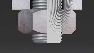
But there's more to them than you might think. And it all starts with the assembly process. Here's a simple bolted joint, where the fastener, in this case a single bolt, passes through holes in two plates and is secured with a nut to complete the assembly.
Let's look closely at what happens when the nut is tightened. As it's turned, the threads on the bolt and the nut engage, and rotation of the nut pulls the bolt threads down, which causes the bolt to stretch. This stretching creates a tensile force in the bolt, pulling the two joined members into contact with one another and compressing them.
The same thing happens for screws in threaded holes, except the tensile force is generated by tightening the screw instead of a nut. This tensile force in the fastener is called preload. It's intentionally applied to the bolt or screw before any external loads that act on the joint.
Preload is surprisingly powerful. It makes the joint stronger, more resistant to fatigue damage, and much less likely to fail. The exact way the preload force works to improve the load carrying capacity of a joint depends on how the joint is loaded.
Joints are usually grouped into two categories - if the load acts along the axis of the bolt it's a tension joint, and if it acts perpendicular to the axis it's a shear joint. Let's look at tension joints first. In these joints, the applied load is trying to pull the two joined components apart.
Without any preload in the bolt the joint begins to separate almost immediately as the load is applied, because the load stretches the bolt. But things happen a bit differently if the bolt is preloaded, because of the clamping force holding the two joined members together. As the load is applied, only a small portion of it is taken by the bolt.
Most of it is taken by a reduction in the clamping force between the two joined members. The exact way the applied load is distributed between the bolt and the clamped components depends on the relative stiffnesses of the parts. The joined members are usually much stiffer than the bolt, which is why so much more of the applied load is used up by reducing the clamping force.
You can think of the joint as an assembly of springs. When the preload is applied, the spring representing the bolt is stretched and held in place, and the springs representing the joined members are slightly compressed. When an external load is applied the springs representing the joined members take most of the load, because they're much stiffer than the bolt spring.
If the applied load increases enough that the clamping force is overcome, the two members move apart from each other. At this point any additional load that's applied to the joint will be taken only by the bolt, right up until failure. Here the joint has failed by fracture of the bolt.
But tension joints can also fail by failure of the joined members, or by stripping of the bolt or nut threads. For design purposes though failure of a tension joint is usually considered to occur once the clamping force has been overcome, because it's likely to fail soon after as any additional loading is applied only to the bolt. In applications where the clamping force is used to maintain a seal, failure might be considered to occur once the clamping force drops to below a critical value, beyond which the seal is no longer considered to be reliable.
As well as helping to keep clamped parts in contact, preload is hugely beneficial for joints that experience cyclic loading and are at risk of fatigue failure, because fatigue life is a function of the applied stress range, not the magnitude of the applied stress. Since the bolt in a preloaded joint only carries a small proportion of the overall load, it will have a much longer fatigue life than a bolt without preload. Let's look at shear joints next, which are very common in structural steel assemblies.
In shear joints the load acts perpendicular to the bolt axis. In this scenario applying preload to the bolt is useful because the resulting clamping force generates a frictional force that resists any sliding between the two joined members. The magnitude of the total frictional force can be calculated in exactly the same way you would calculate the frictional force acting on a block sliding on a surface.
It's equal to the force normal to the surface, multiplied by a coefficient of friction. In the case of a shear joint the force normal to the surface is the clamping force, which is equal to the preload. The coefficient of friction depends on the specific materials being clamped, but in this case we'll assume a value of 0.
3. The frictional force is useful because so long as it's larger than the applied shear force, the bolt doesn't actually see any shear loads - the full shear load is resisted by the frictional force and the bolt is only loaded by the tensile preload force. Joints that are designed to use this frictional force to carry shear loads are called slip-resistant joints.
If the applied load exceeds the frictional force, the joint will slip and the joined parts will come into direct contact with the bolt, which is called bearing contact. In some applications the joint is considered to have failed if it slips. But in others slipping is acceptable.
A shear joint where the load is transmitted directly from the joined members to the bolt by bearing contact, either because the applied force has exceeded the frictional force, or because the joint has intentionally been designed with little or no preload, is called a bearing joint. Bearing joints can fail in a few different ways. They can fail by tensile failure of the clamped material.
They can also fail by bearing failure, where the bearing stress at the contact surface causes an elongation of the bolt hole. Or, if the hole is located close to an edge, the joint can fail by tear-out, where the material around the hole in the clamped part shears. To reduce the risk of tear-out, bolts should be located at least two diameters away from an edge.
And finally bearing joints can fail due to shear failure of the bolt itself, when the shear stress in the bolt exceeds the shear strength of the material. For this type of joint it's best to avoid having the threads of the fastener extend into the shear plane, because the reduced cross-sectional area within the threads will result in a larger shear stress on the bolt, meaning that the bolt will fail at lower loads. Clever design can also help reduce the risk of shear failure of the bolt.
The shear joint configuration shown here is called single shear - there's a single shear plane. But a simple change to the design can result in two shear planes instead of one. Two distinct cross-sections within the bolt are resisting the shear force, so the shear stress in the bolt is halved.
This is called a double shear joint. It allows the joint to carry a much larger shear load. Joints aren't always loaded only in tension, or only in shear.
In many cases a joint will be subjected to both tensile and shear loads, in which case their combined effect needs to be assessed. If for example a joint is mainly loaded in shear, but also has a significant tensile load that acts to reduce the joint clamping force, the frictional force available to resist the shear load will be reduced. Similarly any applied tensile or shear loads that are eccentric, meaning that they aren't aligned with the bolt axis, will result in bending moments acting on the joint.
This can introduce additional shear and tensile loads that need to be assessed. Let's look at an example of an eccentric shear load acting on a pattern of 6 bolts. The applied shear load is distributed evenly between the bolts.
But there's also a moment introduced by the eccentricity of the load. The moment acts about the centroid of the bolt pattern, and introduces additional shear loading on the fasteners, that is proportional to the distance between the fastener and the centroid. There's an important question we haven't answered yet, which is how much preload should be applied to a joint.
It depends on the application, but in many cases the simple answer is that the preload should be as high as possible, although not so high that the clamping force could damage the parts being joined. The main limiting factor is usually the strength of the bolt. A preload value that stresses the bolt to 70% of its yield strength is often used.
The preload force that generates a tensile stress equal to 70% of the yield strength can then be calculated as 70% of the yield strength multiplied by the tensile stress area of the bolt. The tensile stress area accounts for the effect that the threads have in reducing the cross-sectional area of the bolt. Different equations are used to calculate the area for unified and metric fasteners.
A typical M12 structural steel bolt will have a 70% yield preload of around 38 kN. To increase the preload you can either increase the size of the bolt, or you can use a material with a larger yield strength. Preload clearly has a huge impact on how well a bolted joint performs, so we need a way of reliably controlling how much preload is applied to the bolt.
The most common way of doing this is by controlling how much torque is applied to tighten the nut, bolt, or screw. This is normally done using a torque wrench. This is why you see torque values on products or on engineering drawings - it's a way of applying a specific amount of preload to the bolt.
The torque to be applied to obtain a preload F in the bolt can be estimated based on the nominal diameter of the bolt D, and an empirical parameter K, called the nut factor. The nut factor is usually around 0. 2, but will vary significantly depending on the specific application.
This method of controlling preload is used a lot because it's easy to measure torque using a torque wrench. But the problem is that it isn't very accurate. There's a lot happening as the torque is applied.
Friction in the threads, friction under the nut and the head of the bolt, and the use of lubrication all introduce a lot of uncertainty, and as a result using the torque method you‘re likely to get a preload in the bolt that's only within 25% of the targeted value. This is good enough for a lot of applications, but in some cases more accuracy is needed. Another method for controlling preload is to tighten the nut enough to bring the two mating surfaces together, and then turn it through a defined angle.
The angle needed to achieve the desired preload can be calculated based on the thread pitch, the bolt length and the material Young's modulus, or it can be determined experimentally. This is called the turn-of-nut method. It's easy to use, doesn't require any specialist equipment, and the rotation of the nut can be inspected, but it still only has an accuracy of around 15%.
The most accurate method for controlling preload is to measure the elongation of the bolt when the torque is applied, because from there you can easily calculate the force in the bolt. In theory the elongation can be measured using callipers before and after torquing if both ends of the bolt are accessible, but more commonly ultrasonic measurement techniques are used to determine the elongation. Directly measuring bolt elongation allows accurate preloads to be generated to within a few percent of a target value.
One of the berthing systems used on the International Space Station, the Common Berthing Mechanism, uses 16 bolts to connect and create a seal between modules on the ISS. Upon docking each of the 16 bolts mates with a nut, and a torque motor is used to apply a preload force of 90 kN. To accurately control the preload levels, load cells with strain gauges were incorporated into the joint design to measure the elongation of the bolts, because just measuring the applied torque wouldn't have been accurate enough.
A complication when it comes to accurately controlling preload is the fact that the preload in any bolt reduces over time, for several different reasons. One of the main causes of preload loss is embedment, which occurs in the minutes or hours after the fastener is first torqued. When the various surfaces of the joint come into contact, local yielding occurs as the microscopic peaks in the contacting surfaces are flattened.
This reduces the gap between the bolt head and the nut, which can result in a loss of preload. Additional preload loss can also occur over the life of the joint, with factors like in-service vibration loads causing loosening of the joint, or elevated temperatures resulting in creep. To minimise loss of preload it's a good idea to use locking mechanisms like adhesives or special washers to help prevent loosening of the joint, and to re-torque joints after initial tightening and embedment has occurred.
If you want to develop a deeper understanding of bolted joints, one important thing to grasp is exactly how an applied load will be distributed between the bolt and the joined members. A really useful tool for understanding this is the joint diagram. It allows you to visualise the forces and deformations at the joint, and can help you develop a more intuitive understanding of how bolted joints behave.
It didn't quite fit into this video, but I've covered everything you need to know about the joint diagram in a separate video that you can watch right now on Nebula, the creator-built streaming site. I've been posting bonus videos on Nebula that explore specific topics in a bit more detail than in my usual videos, or that cover more niche topics that might not do well on YouTube. There's the one on joint diagrams, but also videos covering dimensional analysis, hydraulic systems, and thermal resistance, for example.
Plus my videos are always released on Nebula a few days early. Nebula was built by a group of independent educational creators as a place outside of YouTube that we have full control over, and where we can share our work without having to worry about advertisers or appeasing an algorithm. It has a great roster of creators, including people like Breaking Taps and Practical Engineering, and is packed with amazing original content that you won't find anywhere else, like the Becoming Human series from Real Science, that explores the early steps in human evolution.
Or Great Cities by City Beautiful, that tells the fascinating stories behind the greatest cities on Earth. There are classes and podcasts on there too. And it's all completely ad-free - Nebula is funded by its subscribers.
So if you'd like to watch my bonus videos, including the one on joint diagrams, sign up using the link below and you'll get a 40% discount on the annual plan, which works out as just $2. 50 a month. Subscribing to Nebula is a great way of supporting creators directly.
By joining you're directly helping me fund the creation of more videos, supporting other educational creators, and helping us build something great at the same time. And that's it for this look at bolted joints. Thanks for watching!
Related Videos

17:58
Understanding Metals
The Efficient Engineer
1,389,009 views
14:49
Understanding Buckling
The Efficient Engineer
836,093 views

20:23
Strongest Bolt? Grades Explained & Dyno Te...
Torque Test Channel
1,177,503 views
15:28
Golden Gate Bridge | The CRAZY Engineering...
Lesics
16,320,919 views

15:53
Why Railroads Don't Need Expansion Joints
Practical Engineering
3,476,533 views

10:39
How Strong Are Bolt Threads? Hydraulic Pre...
Hydraulic Press Channel
1,106,913 views
15:34
Structural Shapes Ranked and Reviewed - Wh...
The Engineering Hub
688,104 views
1:05:21
Bolt Preloading & Torque | Static Strength...
TheBom_PE
120,822 views

23:36
The Incredible Properties of Composite Mat...
The Efficient Engineer
292,288 views

15:53
How Levers, Pulleys and Gears Work
The Efficient Engineer
1,025,017 views

13:44
Understanding Bernoulli's Equation
The Efficient Engineer
3,368,885 views

17:30
Why Bridges Don't Sink
Practical Engineering
1,516,412 views

20:32
Holey Plugs, Batman! But... what are they ...
Technology Connections
5,245,949 views

25:34
How NASA Reinvented The Wheel
Veritasium
13,392,907 views

22:27
How Glass is Made | From Mining Silica to ...
Lord Gizmo
338,232 views

13:09
Mind-Blowing Construction Techniques You D...
Lord Gizmo
163,163 views

14:48
The Big Misconception About Electricity
Veritasium
22,806,155 views
3:46
Bolted joint diagramm explained with 3D An...
MGINEER3D
183,267 views

30:33
Origins of Precision
Machine Thinking
2,507,483 views
![The most beautiful equation in math, explained visually [Euler’s Formula]](https://img.youtube.com/vi/f8CXG7dS-D0/mqdefault.jpg)
26:57
The most beautiful equation in math, expla...
Welch Labs
586,536 views