Vibration Monitoring Proximity Probe Working Principle
106.62k views749 WordsCopy TextShare
Jim Diggins
Working Principles of Vibration Measurement, Axial Thrust and Keyphasor.
Video Transcript:
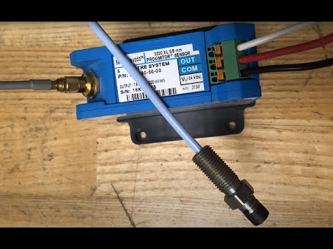
[Music] the basic proximity probe consists of a pancake coil encased in a non conductive protective layer the coil is mounted on the end of a threaded rod a special coax extension cable is typically used to connect the coil to a proximity the proximity is responsible for providing an oscillating signal to the coil which in turn produces a varying magnetic field as metallic objects move into this field induction occurs forming eddy currents the induction results in a loss of power the loss of power is translated as a voltage change on the output terminals of the proximity
the closer the metallic object is to the end of the probe the more induction will occur and therefore the lower the output voltage of the proximity as the object moves away from the end of the probe the output voltage will increase this relationship between voltage and distance is defined as the incremental scale factor of the instrument the most common is F is 0.2 volts or 200 millivolts for every 1 mil of travel this ratio only applies to a specified range of detection the DC output voltage of the proximity is referred to as gap voltage as
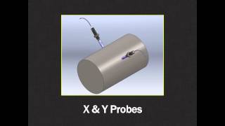
the gap voltage changes the amount of voltage change can be used to track the movements of metal objects the axial float of a rotating shaft can be measured using this gap voltage when used in this type of application the probe is mounted facing the end of the shaft the initial gap voltage setting is established to align the center of the linear range with the center of the total shaft float any axial displacement will create a change in voltage this is detected by the proximity monitoring card alarm points are established to provide warning if the amount
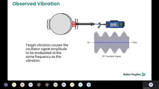
of movement has exceeded the equipment limits another use of this same equipment is the monitoring of rotation speed a proximity probe can be installed over a notched section of a rotating object such as a keyway each time the keyway passes the proximity sensor a change in voltage occurs representing one revolution by applying a time factor to the voltage spikes and equipment rpm can be measured this type of measurement is referred to as a key phasor if you want to measure vibration the DC gap voltage will not work when vibration occurs the voltage will begin to
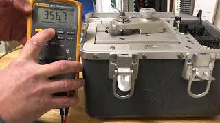
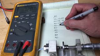
oscillate as the distance between the probe and the shaft changes if you notice on this demonstration this vibration simulator machine is producing a 10 mil oscillation if we roll the wheel slowly the voltage fluctuates significantly however if we energize the motor and bring the wheel up to speed the DC voltage remains very close to the voltage measured at the neutral point of the oscillation this is because the average DC voltage value remains the same if we want to measure this type of movement we cannot use the DC gap voltage if you look at the voltage
oscillation you will notice what we have is an AC sine wave so if you switch the meter to measure AC volts we can now capture the voltage fluctuations of the device however due to the manner in which a basic voltmeter captures AC measurements some math needs to be used to convert this to a usable vibration measurement this process will be covered in a during the dynamic test demonstration the proximity monitoring card which is connected to the output voltage terminals of the proximity will automatically convert this AC voltage to a total shaft travel value in the
unit of Mills proximity probes can also be used on reciprocating compressors to track the amount of band wear that occurs as a piston slides in and out of the cylinder these types of devices are typically referred to as rod drop sensors in this application a proximity probe is installed perpendicular to the shaft either above or below as wear occurs the shaft will drift in relation to the probe producing a change in voltage this measurement is typically taken in conjunction with a key phasor measurement the key phasor is used to ensure the crank is in a
specific orientation each time the rod drop measurement is captured whether the proximity system is tracking rod drop rotation speed axial thrust or vibration the exact same field equipment is used the only thing that changes is the manner in which the signal is interpreted [Music] [Music] you [Music]
Related Videos

4:01
Vibration Probe and Cable Ohm Check, Bentl...
Jim Diggins
66,611 views
1:00:27
Proximity Probes and Other Sensors
Bently Nevada, a Baker Hughes business
45,415 views
6:26
Proximity Probe Dynamic Test Demonstration...
Jim Diggins
48,726 views

8:17
What is a Vibration Sensor?
RealPars
296,767 views

47:54
Introduction to Vibration
Bently Nevada, a Baker Hughes business
17,263 views

39:55
Everything you ever wanted to know about K...
Bently Nevada, a Baker Hughes business
17,426 views

29:25
The Plane That Accidentally Ended Up in Space
Dark Skies
1,004,190 views

13:42
Bentley Nevada vibration Monitoring System...
Sugar Technicals
5,636 views

14:41
Why Do We Use Ground Rods?
Electrician U
250,697 views
16:28
Introduction to Proximity Probes for Vibra...
Riverhawk
85,735 views
3:39
Proximity Probe Static Test Demonstration,...
Jim Diggins
69,438 views

4:57
Installing An Eddy Current Sensor
AMS Reliability
20,301 views
22:18
What Happened to the Capacitors in 2002?
Asianometry
871,610 views
26:29
Watch electricity hit a fork in the road a...
AlphaPhoenix
2,614,927 views

14:07
Position Firing | B-17 Gunner Training Fil...
Armoured Archivist
1,266,105 views

17:37
The Hidden Complexity of Bearing Balls
New Mind
988,624 views

56:26
Gas Turbine | Gas Turbine Working | Gas Tu...
Oil Gas World
2,190,282 views

20:14
MOSFET Explained - How MOSFET Works
The Engineering Mindset
1,879,752 views

16:48
Lefties Losing It: Donald Trump mocks Tayl...
Sky News Australia
628,398 views

20:58
The Surprising Secret of Synchronization
Veritasium
27,233,317 views