[What] Do We Need to Render BILLIONS of Polygons in Real-Time - The ULTIMATE Guide to Nanite
51.24k views5011 WordsCopy TextShare

MARKitekta
Uncover the secrets of real-time rendering with this ultimate guide to Nanite! From the basics of cl...
Video Transcript:
this is the tomb of Pope Julius II in Rome located in the Basilica of San Petro in vinoli and as the central figure we can see the sculpture of Moses Dum by Michelangelo buan Roti with all the intricate details of the body the beard and the sheets one striking feature of Michelangelo's Moses is the depiction of the muscle Contracting as the pinky finger lifts a subtle yet powerful demonstration of his Mastery of anatomy and the Renaissance pursuit of realism the same approach can be observed in the Statue of David Michelangelo captured the intricate network of
veins on David's hand pulsating with tension as he's preparing for the fight against Goliath however many visitors cannot examine these details up close due to proximity restrictions or the sheer size so does the level of detail still serve its purpose from a distance for people who want to experience it firsth hand this poses the question whether detail in Geometry is important if it is not perceivable by The Observer at a certain distance this question becomes more difficult to answer in the scope of rendering where each additional calculation slows down the performance which brings us to
this video's focus on optimizing detail in Virtual geometry we'll explore how to balance realism and performance diving into strategies like level of detail spatial partitioning and Innovative systems like nanite now we are not as skilled with marble as Michelangelo was but we are pretty skilled with digital sculpting and modeling approaches using CAD software from zbrush to 3ds Max or Maya with both organic and hard surface modeling however as with real life examples even in digital modeling we Face the same same challenges as Michelangelo did deciding how much detail is truly necessary when handling highly detailed
geometry the question becomes how can we keep the visual Fidelity without overwhelming computational resources in interior scenes details sculptures ornate furniture and intricate designs can contain millions of polygons each of these adds complexity to rendering increasing the computational load and memory requirements exterior scenes like vast Landscapes or forests introduce even greater challenges millions of polygons or meshes are required to depict leaves trees rocks and terrain at High Fidelity pushing the limits of current Hardware further than what they were meant to do regardless of the scene depiction in reference to highly detailed geometry each portrayal can
cause several problems within the rendering pipeline which we need to explore and try to solve first of which is the draw call as we have mentioned in our lecture previously talking about optimizing the pipeline as a reminder a draw call is a command sent from the CPU to the GPU to render a batch of geometry in scenes with thousands of objects the number of draw calls can Skyrocket leading to Performance bottlenecks as can be seen in this example here each draw call incurs Overhead which refers to the extra work or time required for the CPU
and GPU to coordinate rendering tasks for example each draw call sent by the CPU to the GPU incurs overhead as the two systems synchronize and process commands as a simple example imagine a factory with two workers one preparing parts and the other assembling them if the assembler finishes their task and waits for the next part this idle time is wasted effort analogous to overhead in rendering High overhead from excessive draw calls can cause bottlenecks and rendering the CPU spends too much time preparing commands leaving the GPU underutilized this results in frame drops and reduced performance
another issue we have to take into consideration is the memory aspect that we have talked about in our previous lecture specifically the vram portion of it in that case we talked about going over the texture budget which can quickly exhaust available memory in the vram and cuse extremely poor performance as we have seen in our previous examples High detail geometry requires substantial memory as well especially in vram so when it comes to memory consumption regarding geometry less triangles would definitely mean less memory usage but by how much we can get a rough estimate by looking
at the facts a single vertex requires around 32 to 44 bytes based on the data required for position normals UV coordinates and similar while each triangle takes additional four bytes for each index so 12 bytes in total this means that the best case scenario for a 1 million polygon mesh would be around 30 megabytes and the worst case scenario would be up to 140 megabytes depending on the mass structure alongside memory computational load is massive with an increase in vertex count each triangle in a high detail model requires processing for vertex shading transformation and rization
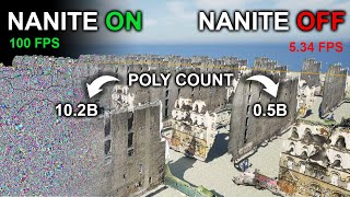
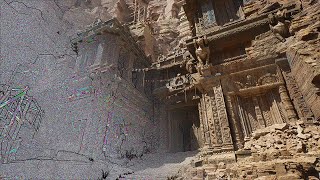
so for millions of triangles this leads to an immense computational burden in each of the stages and then in total the combination of these factors results in frame drops increased latency and reduced visual quality so if we want to maintain 60 frames per second for real-time applications like in this Valley of the ancient demo this can become a significant challenge so what are some of the techniques that were used to handle the issue of highly detailed geometry thus far the most common would be normal baking which is a technique used to preserve the appearance of
high detail geometry on simpler models here artists create a detail High poly model and then bake its surface details like bumps and grooves into a texture this texture called a normal map is applied to a low poly model to simulate surface details without the computational cost of extra geometry in this case we drastically reduce the polygon count while maintaining visual Fidelity for assets ued at medium to far distances however it requires manual labor to model the two mesh versions with the possibility of artifacts occurring if the UVS or projections are not carefully aligned also it
requires additional memory for storing the normal map textures which can still add significant weight to large scenes while normal Maps work well for static surface details they cannot replace the silhouette and broader forms that geometry provides for objects seen at varying distances level of detail or LOD systems are needed to balance performance and Fidelity level of detail or lodd is a technique where multiple versions of a model are created each with decreasing complexity close-up views use the most detailed version while distant views switch to simplified versions which reduces memory due to low vertex count and
absence of B normal Maps while also reducing computation even though it looks like it solves a lot of issues it introduces potential problems like huge time consumption and labor intensive manual creation of lods to simplify models also after generation lods need to be selected and used at appropriate times to ensure seamless transitions which can cause visual artifacts such as sudden popping while switching between different LOD levels disrupting visual immersion finally it creates a storage burden since multiple LOD versions increase memory requirements wouldn't be ideal to have an automated system that adjusts the level of detail
without relying on normal Maps or multiple meshes such a system would eliminate the need for manual labor reduce storage overhead and seamlessly maintain visual Fidelity across all distances one of these approaches would be subdivision modeling that refines geometry by subdividing faces into smaller ones creating a smoother appearance based on the cutl Clark subdivision algorithm this approach is great for effectively creating high quality surfaces without noticeable angularity dynamically subdividing geometry at runtime for consistent visual Fidelity however subdivision is rarely used at runtime and it only adds detail and cannot reduce polygon counts dynamically so it lacks
the flexibility to adjust detail based on proximity or importance which results in increased computational and memory demands especially for complex models in contrast voxels can dynamically adjust detail by representing objects at different resolutions where distant objects can use cors or voxal grids to save memory and computation closer objects employ finer grids to maintain High Fidelity making voxal more adaptable to changing levels of detail in the scene however by using voxelization we struggle with sharp edges and precise geometry because voxels inherently produce blocking representations requiring smoothing techniques to approximate hard surfaces also textures mapped onto voxelized
geometry can be problematic as voxels don't inherently support UVS this often leads to an efficient workflows for applying and blending textures if we sum up all the previously analyzed techniques we can notice that the first two techniques seem to handle the majority of the issues at the expense of manual labor while the second two allow for a more straightforward and dynamic Approach at the cost of other features what's missing is a truly automated system that adapts geometry dynamically without manual interference while maintaining High Fidelity and efficiency in memory computation overhead and draw calls if only
we could virtualize geometry like we did textures we would avoid having all of these issues streaming only the necessary parts of the geometry and not using too much memory and computation on the parts that are unnecessary however this is a much harder problem to solve than virtual textures since geometry is not trivially filterable like textures meaning we can't arbitrarily get one triangle out of four as we managed to do with pixels in textures the same thing was said by Brian Carris at the sigraph conference back in 2021 presenting a solution for it by introducing nanite
a virtual geometry system that builds on a ton of pre previous work done by many talented people interested in developing this field of using highly detailed geometry in real-time rendering however when I saw the lecture I felt pretty confused and then checked the comment section and felt exactly as this person this lecture went from oh yeah makes sense to I have no idea what he's talking about so in order to try and understand how nanite works I embarked upon a journey of trying to understand the key things that make nanite function and when to use
it and I think it all has to do with the four issues we want to optimize which is the reduction of draw calls overhead computation and memory consumption mostly in vram and all these four problems come down to a single question what is the fastest triangle to render because if we can find out the answer to this question we can reduce all of the four issues we had in the past of course the answer may leave you underwhelmed since the fastest triangle to render is the one that is never sent to the GPU as was
quoted in the book The realtime rendering this highlights how important it is to avoid processing unnecessary geometry rendering every triangle in the scene is not just wasteful it's computationally impossible in highly detailed models especially in real-time scenarios so here we see a single statue composed of over 33 million triangles as featured in the nanite in the land of lumen demo 4 years ago while this level of detail is impressive the computational challenge becomes even clearer when you consider an adjacent room was filled with 500 of these statues the sheer volume of geometry in such a
scene would overwhelm any rendering system if processed in its entirety yet much of this geometry would remain unseen or irrelevant making rendering all of it an inefficient use of resources we can address these challenges by intelligently deciding which geometry to skip entirely the fewer triangles we process the better the performance this brings us to the importance of clustering techniques the first thing we need to consider is how to reduce the complexity of our scene checking each triangle each object individually is inefficient and computationally expensive the idea is simple imagine enclosing groups of objects in spheres
or boxes or in this case circles that we will call bounding volumes by testing these larger bounding volumes we can quickly determine if entire groups are visible without processing individual meshes inside them this process eliminates unnecessary calculations this creates a parent child Connection in the form of a spatial data tree or a hierarchy where clusters of objects are treated as single units testing these clusters for inclusion within the camera screen space is significantly faster than checking each mesh individually by organizing geometry into clusters we reduce the computational complexity from n to the logarithm of n
usually we group two to three objects in a proxy so for example in a scene with eight objects rather than performing eight checks a spatial hierarchy allows us to perform just three checks which is the result of the binary logarithm of eight this drastic reduction vastly improves rendering performance bounding volumes are a common clustering method they use Simple geometric shapes like spheres or axis aligned bounding boxes a a BBS to enclose objects or triangles these bounding volumes act as proxies simplifying complex computations such as visibility checks Collision detection and rate tracing in this case we
see aabbs applied for visibility checks in rate tracing however these volumes can also be structured on the level of the entire scene in this case we take the bounding volume of the entire room and divide it into two volumes each enclosing roughly half of the triangles in the scene repeating this process creates progressively smaller volumes down to the smallest boxes containing just six triangles this results in a bounding volume hierarchy or BBH a treelight structure where each node represents a bounding volume and its child nodes enclose smaller subsets of geometry a BBH enables efficient traversal
for rate triangle intersection Collision detection and visibility determination by rapidly eliminating irrelevant geometry this example shows a bounding volume enclosing multiple objects instead of testing every object individually we first check if the ray intersects the B bounding volume if it doesn't we skip all objects inside saving computation if it does we test progressively smaller subdivisions focusing only on relevant geometry however is this tree likee structure only used for organizing geometry into clusters where larger bounding volumes enclose smaller subsets of geometry no it can also be used to establish connections within the tree where one child
node can be shared with multiple parent notes and if that happens the tree is transformed into a directed ayylic graph or dag a dag is a structure where one child node can be shared by multiple parent nodes directed means the connection flows in a specific order from parent to child and a cyclic means there are no Loops or Cycles within the structure in this example the orange geometry is shared between multiple parent nodes transforming the tree into a dag this allows for instancing reusing the same object without duplicating its data which improves memory efficiency and
speeds up performance so can we use this form of clustering and data structure to Aid in our techniques we analyzed previously the best approach would be the manual LOD creation which is memory efficient and computationally effective but it's labor intensive so the question is could we use clustering to somehow automate the creation of different lods if we do that we will have solved the issue of manual labor issue and the one step closer to achieving high level detail geometry in real-time rendering we start by grouping triangles in into clusters of 128 similar to how texels
are grouped in Virtual texturing in their respective myth Maps these clusters make the geometry easier to manage computationally allowing for efficient processing but can we use it for dynamic LOD creation Dynamic L creation would mean that we can join these clusters and simplify them to get even easier processing and detail reduction at varying distances from the objects as clusters get further from the camera we reduce their complexity by grouping them together for example we can join two clusters and simplify them by 50% collapsing edges to remove unnecessary triangles as we have discussed previously we can
use tree likee data structures to ease the cluster joining process in this way we always have locked cluster boundaries this approach while efficient can cause cracks along cluster boundaries due to mismatches between level of detail which we call mashru mashcraft is a common problem with tree like structures where locked edges accumulate and fail to simplify properly because the cut along the LOD tree does not intersect any of the cluster boundaries as can be seen in this example here adag solved this issue by sharing child clusters between parent nodes by locking boundaries during simplification and unlocking
them in subsequent levels dags prevent cracks and ensure smooth transition between lods how is this done we start by picking a group of end clusters shown here in red green blue and yellow and merging them into a single simplified representation during this process the boundary remains unchanged to ensure consistency with neighboring clusters once simplified the merged cluster is split into smaller clusters and the amount of clusters for example is half of the initial number which was four thus forming a new level of detail the directed ayylic graph at the bottom shows how these clusters share
connections this dag enables consistent decisions for simplification while avoiding cracks or crff buildup it is visible that you cannot draw a straight line through the dag and avoid cutting one of the connections which is why we avoid the emergence of cracks now only thing that is left is determining when to join them together this short GIF illustrates how clusters are grouped and simplified across multiple levels where at each level the boundaries of the previous clusters become the interior of the new larger clusters which ensures that locked edges don't persist across levels avoiding the accumulation of
dense triangle cruft now we have a way to merge neighboring clusters but is that enough while clustering and simplification reduce geometry effectively linearly simplifying meeses still leaves too many triangles we need to improve the logarithm of n cluster further since a large amount of clusters can overwhelm the system especially in real-time rendering of large detail scenes we need a rule to simplify geometry further no triangle should be larger than a single Pixel when rendered this ensures that even if errors occur during simplification they are imperceivable at the pixel level it also optimizes performance without sacrificing
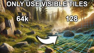
visual Fidelity to determine the level of detail needed for a mesh screen space error calculates how much a simplified mesh deviates from the original based on its size and pixels if the error is too large the mesh switches to higher detail version to maintain visual quality as is shown in this example here this approach creates an automated LOD system that pre-processes clusters into a hierarchy at runtime only visible geometry is loaded reducing memory usage and computational demand while maintaining High visual Fidelity even with automated lods the sheer number of clusters in large scenes poses a
CH challenge due to the huge amount of draw calls per cluster or per mesh consisting of several clusters so what do we do we can combine all clusters into a single geometry reducing the number of draw calls instead of rendering hundreds or thousands of objects separately the GPU processes them as one single call materials remain separate because they can't be automated but geometry is optimized for performance in a significant way still if we joined all the Clusters into a scene into one geometry we would still have a lot of work to do so we have
to introduce calling techniques to call means to remove from the flock and in computer Graphics calling techniques aim to eliminate geometry that doesn't contribute to the final image by combining automated lods with a single draw call and effective calling we further reduce the workload and optimize real-time rendering so let's check this part out basically we can introduce three types of calling which are the frustum calling the backp calling and the occlusion calling where each is important on its own but it's better if we go in a specific sequence starting with the froom culling which ensures
that only objects within the camera's view are rendered geometry outside this volume is ignored reducing the number of objects processed the camera's view is represented by the canonical view volume or frustum a truncated pyramid shape and instead of testing every triangle we use bounding volumes like spheres or axis aligned bounding boxes like we mentioned previously to simplify visibility checks this diagram shows how objects inside the frost are processed cessed while those outside are cul this dramatically reduces computational effort especially in complex scenes however it doesn't address objects that are inside the frost them but hidden
behind others which is when we can introduce backface cing which is a technique that is used to remove triangles that face away from the camera all back-facing triangles that are part of a solid opaque object can be called away from further processing assuming the camera is outside of it and does not penetrate the object backface calling can performed by using screen space calling where we determine the triangle orientation by analyzing the sequence of indices if the indices are ordered clockwise in screen space the triangle is visible and if it's not it is called the other
approach is view space calling where we use the normal Vector of the triangle if the normal points away from the camera the triangle is called by Computing the dot product of the viewing vector and the triangle normal both methods ensure that triangles facing away from the camera are skipped reducing unnecessary computations while frustum and backf calling are efficient they don't account for uded objects for instance a object behind a wall might still be processed even though it's not visible this is where more Advanced Techniques like occlusion calling come into play occlusion calling is similar to
frost calling but instead of keeping objects within the frustum we call those objects out it uses occlusion volumes like spheres or bounding boxes to test whether objects are visible these occlusion volumes are snugly fit within the objects and then used based on their silhouette in the screen space to create the occlusion frust this approach provides a valid occlusion coling technique but still has two major limitations for example if we have two adjacent occluders the blue boxes here their occlusion frustums do not occlude the Box behind it entirely which is why it is still used for
processing even though it is not visible another issue regarding this approach is what is an occluder we can set some conditions to determine this like it is opaque it has a significant size in screen space or it has a significant amount of polygons however these conditions are not precisely defined and hence can lead to inaccurate assumptions and hence results this approach is an object space calling technique but there is one that is much more simpler and that is the image space coling technique where we use the depth buffer or the zbuffer as we might know
zbuffer is simple and Brute Force where we check everything that is in the scene and test its distance from the screen space plane storing depth per pixel without the zbuffer scenes would render incorrectly objects would overlap unrealistically with parts of objects appearing in front of others when they shouldn't this creates visual artifacts and breaks the illusion of depth in 3D rendering to resolve this the zbuffer ensures that only the nearest surfaces are visible creating a realistic depth representation but there's a catch we need the zbuffer to decide occlusion but we also need the occlusion to
draw the zbuffer and here we run into a problem of deciding what do we draw first to solve the zbuffer dependency ISS we use a hierarchical z buffer or hzb which is similar to a MIP map for textures but the Z depth buffer is down sampled progressively each pixel in the higher MIP level represents the highest depth of the four pixels in the lower level not an average this hierarchy simplifies visibility checks while retaining critical depth information using hzb we can check the visibility of abounding volume for our clutter we start with the higher level
mips 4x4 pixels for example for coer checks if the result is ambiguous we refine the test with a lower level MIP for higher resolution HCB isn't rendered at the highest resolution saving computational time while efficiently solving occlusion but is this enough for nanit colink needs nanite improves Upon This by implementing occlusion in two passes in the first pass bounding volumes of all significant objects including previous occluders and possibly large clusters are checked against the previous frames hdb in the second P new geometry or newly entering objects are tested against the updated current frames HCB for
refinement and this ensures we only draw what's necessary optimizing performance by a significant amount however we can still have one major problem and those are the small triangles that can occur in the Clusters which are very inefficient for rendering the main reason for this is that the fragment Shader processes triangles using a 2X two pixel quad if a triangle doesn't fully cover the quad the Shader dis regards up to 75% of its work wasting GPU resources this is why it's very important to use use proper topology on meshes where Emil has shown in his post
that maximizing the area of the triangles in a mesh contributes to better performances since it minimizes the GPU work that is not utilized in the end we can address this problem by cutting triangles that don't contribute significantly to the scene triangles smaller than a pixel or triangles that are elongated where their bounding rectangles don't overlap with the center of a pixel can be skipped to avoid unnecessary fragment Shader overhead but there is a problem the GPU is a hardware rest rizer and approaches every triangle in the same way so what can we do we can
use a software rizer which handles these cases by running a specific optimized code on the GPU by doing so we are handling small triangle cing efficiently without relying on generic GPU processes to ensure smooth rendering even in highly detailed scenes this is exactly what Nan did for clusters with edges less than 32 pixels they use a software rizer and for the others they use the hardware rizer which made rization process three times faster so using all these techniques can help us achieve great performance while visualizing large scale environments with high geometric detail Nite is ideal
for scenes with billions of triangles such as large terrains or detailed assets that we can kit bash together into a coherent narrative it simplifies rendering by dynamically adjusting lods based on the viewer's distance however issues such as overdraw can occur in scenes using nanite when overlapping geometry causes the same pixel to be shaded multiple times a common issue in complex SC with distant layered elements so manite does not solve all the problems and can cause issues if not used properly so where should we use it manite should be used with scenes containing extremely high poly
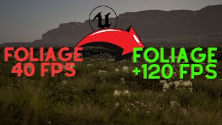
assets like photogrametry or detailed architectural models basically where large static objects like rocks walls and structures act as primary occluders on the other hand when you have dynamic or animated objects in the scene or transparent or mask materials and even aggregate geometry like foliage it can create a lot of draw and perhaps traditional scene complexity reduction approaches should be used in this case so if you have a simple geometry scene with minimal details you can use the standard pipeline but if you introduce opaque High poly assets you should use nanite to optimize LOD and performance
and avoid using it when you have very small and detailed Dynamic objects but is geometry the only challenge in achieving realism geometry defines the shapes and surfaces of our world but there's another critical element and that completes the picture light lighting is perhaps the most essential element in making scenes feel alive and immersive real-time Lighting systems have traditionally relied on baked lighting or static setups which are great for predefined environments but fail when the scene is dynamic or the light changes Global illumination where light bounces between surfaces creates realistic lighting but traditionally it's been computationally
expensive making it impractical for real-time applications so what if we could have fully Dynamic lighting that behave like it does in the real world bouncing scattering and interacting with surfaces in Real Time Imagine A system that not only adjusts to every change in Geometry but also simulates like Behavior accurately even in highly complex scenes this is where Lumen unreal engines realtime Global illumination system steps in but that's a topic for another day creating this video took countless hours of research scripting editing to bring you an engaging and comprehensive look at nanite and its incredible capabilities
but here here's the thing we've only scratched the surface of the techniques and Innovations shaping the future of realtime rendering if you found this video helpful or even just interesting liking the video and leaving a comment doesn't just help the video it helps others Discover it and ensures the accuracy and Clarity of the content by gathering feedback from curious minds like yourself every bit of Engagement helps this video reach a wider audience allowing us to share knowledge and Foster discussions about the topic of virtual geometry systems like Nite I would like to thank you for
your time and hopefully see you in the next video bye
Related Videos
8:43
Is Nanite REALLY Worth It? Simple Test of ...
MARKitekta
8,975 views
27:52
How To Use Less Memory for More Realistic ...
MARKitekta
19,100 views

20:31
Unreal Engine Sucks? You're doing it wrong
Dallas Drapeau
45,542 views

13:48
How To Learn Any Skill So Fast It Feels Il...
Justin Sung
1,546,141 views

22:29
Microsoft Announces World's First Topologi...
Dr Ben Miles
1,109,142 views
21:00
Epic's Unreal Engine Foliage Optimization ...
Gatyh Interactive
7,942 views

18:09
Better Mountain Generators That Aren't Per...
Josh's Channel
495,417 views

24:07
Jon Stewart on Trump’s Heel Turn on Zelens...
The Daily Show
1,097,107 views

23:40
How Games Have Worked for 30 Years to Do L...
SimonDev
1,468,420 views

27:30
Forward and Deferred Rendering - Cambridge...
Ben Andrew
28,017 views

58:41
Coding Adventure: Rendering Fluids
Sebastian Lague
651,078 views
35:33
I Tried Rendering Millions Of Particles
Acerola
405,300 views

21:46
Surface-Stable Fractal Dithering Explained
runevision
365,999 views

12:11
Why Unreal Engine 5.5 is a BIG Deal
Unreal Sensei
1,884,717 views

21:33
How Path Tracing Makes Computer Graphics L...
Computerphile
58,720 views
7:20
Why Do We Need Polygons In 3D Video Games?
gameranx
1,257,730 views
1:10:00
A Deep Dive into Nanite Virtualized Geometry
SIGGRAPH Advances in Real-Time Rendering
254,914 views

20:26
TRUMP ENTRÓ EN PÁNICO! CANADÁ Y MÉXICO GOL...
Daily Brief
449,135 views

22:09
Nanite for Artists | GDC 2024
Unreal Engine
112,025 views

22:40
An introduction to Shader Art Coding
kishimisu
1,082,436 views