How To Convert DC to AC | Direct current Inverting | 3D Animation
1.34M views1470 WordsCopy TextShare

Prof MAD
#dctoacinverter converter #dctoac #directcurrent #alternating_current #electronic
In this video, w...
Video Transcript:
Welcome to Professor Mad. Electronics for beginners. Today, we are going to talk about, “how to convert direct current into alternating current”.
Electric current refers to the rate of electrons moving in an electronic circuit. If, this many electrons are moving through the circuit at a second, we can say the electric current of this circuit is 1 Ampere. Even though the electrons flow from negative terminal to positive terminal, in most of the textbooks, Conventional Current assumes that current flows out of the positive terminal, through the circuit and into the negative terminal of the source.
This was the convention chosen during the discovery of electricity. It was not quite accurate. We have unfortunately stuck with this convention to this day and so current flow from positive to negative is called, “conventional current flow” and is used when drawing circuit diagrams.
In fact, it makes no difference which way current is flowing as long as it is used consistently. The direction of current flow does not affect what the current does. Throughout this video we use the term Current for the conventional current.
There are two forms of electric current. Alternating current (AC) and Direct current (DC). One is not better than the other as both are necessary.
Here we will explain each of them and how to convert Direct current into alternating current. Let's start with direct current. DC is a linear type of electrical current.
Direct current always only flows in one direction. From positive pole to negative pole. Keep in mind that the electrons flow opposite to that.
For DC, the positive and negative poles always remain the same. We can draw a graph for the magnitude of direct current with the time, like this. Since the current does not flow in the opposite direction, the graph only has a positive side.
DC powers appliances with delicate electronic circuits, that require a simple and steady current flowing in one direction. Nowadays, this type of current powers cellphones, computers, and most other electronics. And the current obtained from batteries, solar cells, etc.
How does AC work? Alternating current (AC) is an electric current which periodically reverses direction and changes its magnitude continuously with time. AC constantly changes its flow between positive and negative terminals.
This means that electrons also change their flow, following the negative to positive end as the polarity changes. We can draw a graph for the magnitude and direction of alternative current with the time, like this. Since the current changes its direction periodically, the graph has both positive and negative cycles.
The speed at which AC changes polarity and completes several cycles in one second is called frequency, And it is measured in Hertz. The most common AC wave form that is used in Electrical and Electronic Engineering is the Sinusoidal Waveform. However, an alternating AC waveform may not always take the shape of a smooth shape based around the trigonometric sine or cosine function.
AC waveforms can also take the shape of either, Square Waves, Triangular Waves or any other complex shape. Standard AC found at most of our homes, is a 120V amplitude pure sine wave with a 60Hz frequency. However many appliances and electronics use direct current (DC), which provides consistent power to the device.
We explain how to convert AC in to DC in our previous videos. On the other hand, most renewable power generation systems such as solar PV systems and wind generators involve DC. So it is important to convert this generated DC into AC for distribution purposes.
In today's video we are going to talk about, how to convert DC to AC, or inverting the DC. Just imagine you have a DC battery that can supply direct current and someone taps you on the shoulder and asks you to produce AC instead. How would you do it?
If all the current you produce flows out in one direction, what about disconnecting the wires? The current becomes zero, Then lets flip it back. Now we have current that flows in the opposite direction.
Like wise we can change the wires back and forth, so the current direction keeps reversing. What you end up with is very abrupt changes of current: All in one direction, all in the other direction, and back again. Look at the graph of the current against time.
You'll get a square wave. Although electricity varying in that fashion, technically, its an alternating current. Instead of swapping the wires, we can do this by using four switches.
Switching your current in given manner on and off, very rapidly, would give pulses of direct current. We call this as H-bridge arrangement, which would do at least half the job. To make proper AC, you'd need a switching H bridge arrangement that allowed you to reverse the current completely, and do it about 50‐60 times every second.
Visualize yourself swapping your switches back and forth over 3000 times a minute. That's some neat finger work you'd need! That is why we use the fastest switches in the world, "Transistors".
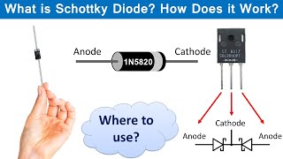
We can use transistors, more specifically "Insulated Gate Bipolar Transistors or IGBTs". The most common IGBT switching frequency ranges from 20 to 50 kHz. An IGBT is a three-terminal power semiconductor device, primarily used as an electronic switch.
IGBT can be switched ‘ON’ and ‘OFF’ by activating and deactivating the gate. If we make the gate more positive by applying voltage across the gate, current can flow from the collector to emitter, so the IGBT in its “ON“ state. If we make the gate negative or zero, the current flow stops and IGBT will remain in “OFF” state.
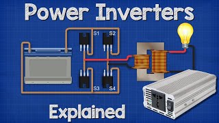
We can use IGBTs as switches. At its simplest, an inverter consists of what is known as a H-Bridge arrangement. This circuit illustrates the implementation of a single phase H-Bridge circuit using four IGBTs.
The operation of the H-bridge is straight forward. By closing A and B, and opening C and D at the same time, current starts to flow through the bulb from left to right. By opening A and B and closing C and D at the same time, current starts to flow through the bulb from right to left.
Likewise by turning ON and OFF the IGBT switch pairs, reverses the current direction. That means Alternating current is generated. To work these IGBTs correctly, accurate control signals must be provided to A, B, C and D.
These control signals are generated by a separate circuit, which can control the frequency of the output AC signal. As an example, we can use a cheap arduino board to supply these controlling signals. Even though we converted the DC to AC square wave, it's not at all like the AC sine wave supplied to our homes, which varies much more smoothly.
To avoid damaging the IGBTs at short circuits, when changing polarity it is necessary to turn OFF one set of IGBT before turning on the next. During the transition, all the IGBTs must go OFF at one point. We normally use a Diode with an IGBT, to provide a necessary path for inductive current in order to limit potential voltage build up during the transition period.
We can use a capacitor to smooth out any variation in the d. c. supply.
AC square waves are very abrupt, and can end up damaging some delicate electronics in your home. To solve this, manufacturers invented rectification devices that modify the wave, creating what is known as a modified sine wave (MSW). As the name suggests, modified sine wave is not really a true sine wave at all.
It is simply a stepped wave, like this. While MSW is better than a square wave, it is still not a pure sine wave, which is required to power certain delicate electronics. In a modified square wave design as shown above, the square waveform shape basically remains the same but the size of each section of the wave-form is appropriately dimensioned so that its average value matches closely to an AC waveform’s average value.
As you can see there's a proportionate amount of gap or null areas between each square blocks. These gaps ultimately help to shape up these square waves into sinewave like output. Further developments in the industry allowed for the creation of rectification circuits, giving way to the creation of pure sine waves.
So as we describe there are 3 major types of inverters. square wave, modified sine wave and pure sine wave. Square wave type is the most basic and cheapest one and the pure sine wave is the most complex and costly one.
You can select one type according to your requirement. If you enjoyed this video and want to hear from us again, be sure to hit that like button and Subscribe button before you go. Thank you.
Related Videos

9:57
Blinking LED circuit or Astable Multivibra...
Prof MAD
161,086 views
13:39
Power Inverters Explained - How do they wo...
The Engineering Mindset
3,770,870 views

6:08
Network Security News Summary for Wednesda...
Internet Storm Center Stormcast
7 views

10:16
How an Inductor Works ⚡ What is an Inductor
VirtualBrain [ENG]
853,945 views

7:15
How to convert AC to DC | 3D Animation
Prof MAD
1,580,960 views

6:56
Inverters, How do they work?
Sabins Civil Engineering
4,944,456 views

12:55
How to use a multimeter like a pro, the ul...
James Gatlin
2,794,730 views

14:41
How 3 Phase Power works: why 3 phases?
The Engineering Mindset
2,051,659 views
8:58
What is a Schottky Diode? How Schottky Dio...
Electrical Electronics Applications
867,842 views

20:39
Power factor explained | Active Reactive A...
Prof MAD
535,282 views
18:09
Fishing life hack idea that few people kno...
FISHING knots
22,073 views
10:36
Why Use AC Instead of DC at Home??
ElectroBOOM
5,540,549 views

8:58
how to make simple inverter 4500W , sine w...
inventor KR
12,280,517 views
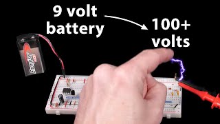
16:32
Let's build a voltage multiplier!
Ben Eater
2,315,664 views
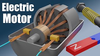
10:03
How does an Electric Motor work? (DC Motor)
Jared Owen
19,639,822 views
8:06
How to Make a Variable Power Supply Using ...
ZAFER YILDIZ
240,811 views

22:02
Just 20 minutes! Turn bicycle axles into s...
Tips 365
74,414 views

18:17
Stop Wasting Money on New Batteries! Resto...
DIYTechTrends
29,031 views

17:36
Capacitor Explained : Calculations | Serie...
Prof MAD
257,007 views

5:50
Capacitor working animation | Dielectric p...
Jan visual physics
335,839 views