Shaft Design for INFINITE LIFE and Fatigue Failure in Just Over 10 Minutes!
91.08k views2131 WordsCopy TextShare
Less Boring Lectures
DE-Goodman, DE-Morrow, DE-Gerber, DE-ASME, etc.
Mean and Alternating Stresses,
Fatigue Failure,
Infi...
Video Transcript:
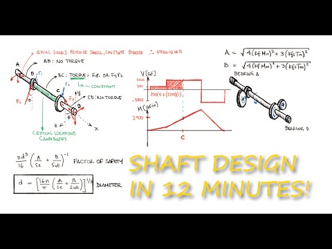
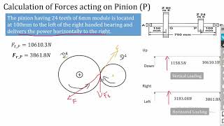
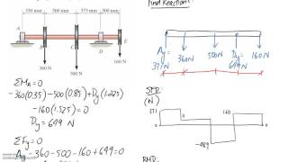
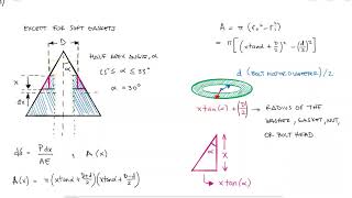
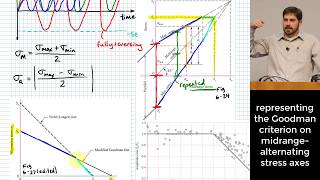
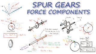
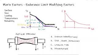
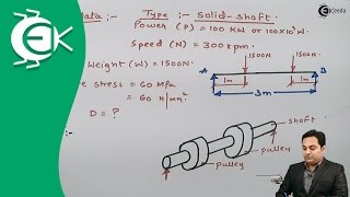
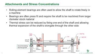
just as with the analysis of any structure subjected to static loading evaluating the stresses in every section of a shaft is not required an analysis in only a few critical locations is enough specifically for shafts these critical locations will be on the outer surface where shearing and bending moments are highest at axial locations where the bending moment is large wherever the torque is present as some sections of the shafts do not carry any torque with them and wherever stress concentrations exist in today's video we will use everything we've learned about fatigue in the previous four main videos links below to derive and use some equations that will help us either evaluate the factor of safety for shafts or more importantly calculate a reasonable shaft diameter for our design a simple free body diagram can illustrate how only sections of shafts carry the torque that is transmitted from one gear to another or from one pulley to another or any combination of torque transmission elements identifying where the torque exists will narrow down where the critical locations happen worth pointing out here is that since the torque is relatively constant when the system is operating at a steady state the shearing stresses due to shearing will also be constant this will be important later the bending moments can be determined using shear and bending moment diagrams since the contact forces between gears or the pulley orientation can occur at an angle the shear and bending moment diagrams are usually needed in two orthogonal planes although in some very unusual cases a slanted plane will be enough using basic vector addition from physics and algebra the resulting moments can be obtained from the critical location candidates as well as the direction and orientation at which they occur axial stresses that result from components that cause or withstand axial loads like tapered roller bearings or helical or bevel gears are usually negligible compared to the normal stresses from bending and they are usually also constant so in terms of fatigue they don't contribute much however if there aren't any external axial loads it would not be reasonable to assume the normal stresses due to axial loading are zero transverse shearing stresses just like any other structure under static or cyclic loading will also be negligible when the component is not particularly short linked below if you want to check that out and since shafts are usually not very short beams transfer shear is in fact negligible therefore taking into account only normal stresses from bending and only shearing stresses from torsion we can write general expressions for the mean and alternating stresses including fatigue stress concentration factors in terms of the mean and alternating moments and torques assuming solid round cross section shaft we can write these expressions in terms of the diameter for a stress element with a sigma x for bending and at tau xy for torsion we can find the principal stresses and it works for both the alternating and the mean values using more circle i can find my principal stresses sigma 1 sigma 2 and sigma 3. and with the principal stresses we can evaluate the von mises stress from the distortion energy method we do all of this so that we can quote unquote combine the normal and the shearing stresses into one von mises stress and we do this for both the alternating stresses and the mean stresses we substitute the values sigma 1 sigma 2 and sigma 3 we distribute the squares we cancel out terms and simplify others and we find an expression for the von mises stress for any element subjected to a normal stress and a shearing stress which is the case of a shaft and this is true for both the alternating and the mean stresses the von mises stress for the alternating stresses is what we would compare to the endurance limit and the von mises stress for the mean stresses is what we would compare to the ultimate strength yield strength or true fracture strength of course depending on the fatigue failure criterion but we can go one step further we can write the von mises stresses in terms of moment torques fatigue stress concentration factors and diameter by factoring out the common terms and defining capital a and capital b variables as the remaining expressions within the parentheses we can write expressions for each one of the fatigue failure criteria like for example d e goodman and also solve for the diameter which is very helpful for design purposes notice that the diameter expression is even in terms of the fatigue factor of safety and that we call the criteria d e goodman or d e morrow etc because we used distortion energy to get the resulting stress the von mises stress for both alternating and mean stresses as always with any cyclic loading calculations you should always first check for yielding during that first cycle the maximum stress will be the absolute value of the mean stress plus the alternating stress for both the normal and shearing stresses the corresponding maximum von mises stress would then be compared to the yield strength for a factor of safety for yielding value let's look at an example where we evaluate the fatigue factor of safety for a given shaft application a steel shaft with two diameters is rotating on bearings a and e and it's transmitting a torque from gear b to gear d we would like to evaluate the fatigue factor of safety using the d e morrow criterion i know that for any criterion i'm using i will need to know the properties of the material as well as the mean and alternating stresses within the shaft if you remember from our previous video link below the moral criterion compares the alternating stress to the endurance limit and the mean stress to the true fracture strength therefore i will need the endurance limit and the true fracture strength however since i need to calculate the fatigue stress concentration factors and to do that i need to find the notch sensitivity values q and qs and at the same time those are functions of the ultimate strength i will also need the ultimate strength value now this process won't change from what we've done for many practice exercises i would look up the ultimate strength and the true fracture strength of the material and with an se prime estimate a surface factor that depends on how the shaft was manufactured a size factor for a diameter of 2. 5 inches for a rotating rod a loading factor of one since i'm using the von mises stress for the combination of stresses and no temperature or reliability factors i would be able to have an appropriate estimate for the endurance limit so for the purposes of this example we'll focus on the stresses as we already know how to carry out the other process for the stresses particularly for the variables capital a and capital b from the expressions that we derived today and that are used for all of the different criteria expressions i know that i will need the alternating moment and torque the mean moment and torque and the fatigue stress concentration factors for normal and shearing stresses so to recap to evaluate the fatigue factor of safety using the demoral criterion i need the endurance limit the true fracture strength and for the a and b variables i will need the mean and alternating torques and moments and the fatigue stress concentration factors the internal torque from b to d can be found by multiplying the tangential force on the gear times its radius for any of the two gears if the torques were not the same at the two gears the sum of torque would not be zero and therefore the shaft would be accelerating or decelerating additionally since these forces don't change and therefore the torque remains constant i can conclude that the alternating torque value is zero and that the torque that i already calculated is equal to the value of the mean torque looking at the free body diagram i can calculate the reaction forces at a and e by knowing that the sum of moments about a is equal to zero since the shaft is not rotating about a for this i would find a positive moment from the force at b a negative moment from the force at d and a positive moment from the force at e from a sum of forces in the y direction and assuming r a is a positive reaction i would be able to solve for that reaction with these values i can create shear and bending moment diagrams knowing that where the maximum moment occurs there is no stress concentration and the diameter of the shaft is large at two times the diameter of the smaller section of the shaft i know that the location where the maximum normal stress from bending occurs is at the fillet c as the shaft rotates any element on the surface of the shaft will go from a negative to a positive moment value of 2400 pound inch with a mean value of zero as any element on the surface would go from compression to tension as the shaft rotates all there is left is to calculate the fatigue stress concentration factors for both normal stresses and shearing stresses the first thing i need is the stress concentration factors for static loading kt and kts we find these by looking up stress concentration factors for a round shaft with a shoulder fillet for both torsion and bending with a large diameter of 5 inches and a small diameter of 2.
5 inches my capital d over lowercase d ratio is equal to 2. and with a notch radius of 3 16 of an inch the r over d ratio is 0. 125 for kt a value 1 3 of the way from 1.
5 to 3 for the d over d ratio would result in 1. 6 for kts for an x axis value of 0. 125 on the d over d curve of 2 would give me a value of 1.
4 remember at the beginning of the example how i mentioned we were gonna use the ultimate strength this is where we'll use it since the notch sensitivity value q and qs depend on the ultimate strength even though the notch radius value is not found within the range of these plots we see that the values for q and q s plateau as the notch radius increases for an ultimate strength value of 100 ksi the q value for high radius values can be assumed to be 0. 85 and for the qs value closer to 0. 9 i will assume a value of 0.
88 finally using the expressions that we developed a couple videos ago link below i would be able to calculate the fatigue stress concentration factors for both normal and shearing stresses try to be as accurate as possible when reading these plots and try to be conservative when selecting a value any time you're unsure now going back to our a and b expressions and knowing that the alternating torque is zero and that the mean moment is zero their expressions are simplified by substituting the values that we found and using those a and b values in the factor of safety expression we find that the fatigue factor of safety using the d e morrow criterion is 5.
Related Videos
![[WATCH THE NEW CORRECTED ONE] Shaft Design - Moments in 3D Orthogonal Planes - Example 1](https://img.youtube.com/vi/CvPU9lUkJ_c/mqdefault.jpg)
3:15
[WATCH THE NEW CORRECTED ONE] Shaft Design...
Less Boring Lectures
8,422 views
10:41
Power Screws - Torque to Force Relationshi...
Less Boring Lectures
97,627 views

1:27:08
Shaft Fatigue Factor of Safety using ASME ...
TheBom_PE
49,425 views
7:09
Video Bearing Load Calculations
Aaron Schellenberg
70,509 views
11:35
Fatigue FAILURE CRITERIA in Just Over 10 M...
Less Boring Lectures
73,762 views
24:10
Shaft Carrying Gears | Design of Shafts | ...
The Mechanical Engineer
18,002 views
11:22
Mechanical Springs - Stress, Deflection, a...
Less Boring Lectures
50,806 views

16:18
Understanding Failure Theories (Tresca, vo...
The Efficient Engineer
2,240,821 views
9:37
(11-2) SFD & BMD with Graphical Method #1
The Ryder Project
27,148 views
12:32
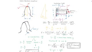
LEWIS BENDING STRESS at the Teeth of a Gea...
Less Boring Lectures
20,542 views
11:07
Bolt (Fasteners) and MEMBER STIFFNESS in J...
Less Boring Lectures
26,284 views
1:00:54
Midrange and Alternating Stress | Goodman ...
TheBom_PE
48,452 views
12:52
Gear Forces and Power Transmission of SPUR...
Less Boring Lectures
45,530 views
12:34
Marin Factors for ENDURANCE LIMITS in Just...
Less Boring Lectures
18,248 views
16:33
Problem 1 on Design of Shaft - Design of S...
Ekeeda
602,817 views

17:58
The Incredible Strength of Bolted Joints
The Efficient Engineer
3,161,236 views
35:09
L17 Shafts - Shaft Design
Joshua Tarbutton
16,499 views

15:53
How Levers, Pulleys and Gears Work
The Efficient Engineer
1,082,140 views