BPMN Process Map Tutorial and EXAMPLE
46.3k views2412 WordsCopy TextShare

The Business Analysis Doctor - IIBA Certification
BPMN, formally Business Process Model and Notation is one of the most widely used methods for busine...
Video Transcript:
want to learn more about the standard for business process modeling if so check out this lesson on bpmn hey Doc Squad Dr White here with the business analysis doctor today I'm giving you a tutorial on bpmn or business process modeling notation but before we get started if you want more business analysis training and tips be sure to subscribe to the page and turn on the notification Bell with that said let's get started bpmn stands for business process model annotation this modeling method is used across both business and it domains and is increasingly becoming an industry
standard now let's talk about what you'll learn we'll talk about what bpmn is we'll discuss the main components of bpmn we'll look at some vpmn rules best practices and then we'll take a look at a bpmn model so what is bpmn bpmn is a process modeling notation created to standardize the graphical representation of business procedures transactions and business collaborations bpmn is used to only specify business processes it's used to define and understand business procedures to facilitate the understanding amongst all stakeholders it's also used to illustrate internal and collaborative processes it's also used to clarify internal
and external participant roles as well as facilitate workflow automation there's four main element groups in bpmn this includes flow objects connecting objects artifacts and participants flow objects include events activities and gateways the first type of flow object we'll look at is events an event is something that happens during a process they affect the flow of the process and usually have some Trigger or impact there are three main types of events start events indicate where a particular process begins this event will not have any incoming sequence flows start events are presented as circles and must be
drawn with a single Thin Line next we have our intermediate events an intermediate indicates where something happens between the start and the end of a process it usually affects the flow of the process but will not start or directly in the process intermediate events are presented as circles and must be drawn with a double Thin Line an end event indicates where a particular process ends this event will not have any outgoing sequence flows as it terminates the process and events are presented as circles and must be drawn with a single thick line there are several
markers that can be used to represent the different dimension types of events but these are the most common a message event indicates that a message is sent to or from a participant a timed event indicates that a specific time date or specific cycle can trigger an event the era event indicates that some type of exception is interrupting or ending the process it's represented with the lightning bolt symbol the cancel event is used when a transactional sub-process is terminated without being completed this Dimension is represented with an X and cannot be used for a start event
the terminate event indicates that all activities in the process should be immediately ended this event is represented by a circle with a thick black line and a dot in the middle this type of Dimension can only be used for end events now let's look at activities activities represent the work that a company performs within a process they are presented as rectangles with rounded corners there are two main types of activities a task is an atomic activity within a process flow it involves work that cannot be broken down to a finer level of detail a sub-process
is an activity whose work can be broken down to include more details such as subsections phases or layers the internal details of a sub-process can be modeled using activities gateways events and sequence flows the sub process is an object within a process but it can also be opened up or exploded to show a lower level process like the task object the sub process is Illustrated as a rectangle with rounded corners but it also includes a small box with a plus sign when the plus sign is selected it leads to the more detailed process activity should
be labeled with the verb noun format to indicate the action that is being taken as well as the object that is involved for example submit order or send email now let's discuss gateways a Gateway is used to control the splitting and joining of sequence flows in a process the general icon for a Gateway is a diamond but there are several internal markers that indicate a particular type of control over the flow here are the most common types of gateways an exclusive or default gateway is used to create alternative paths within a process flow this is
a decision point for the process for a given decision only one of the paths can be taken an exclusion is considered to be the default gateway because it's used most commonly it can be represented as an empty diamond or a diamond with the X marker generally each outgoing path needs to be labeled to describe the condition that must be met the event base Gateway represents a branching point in the process where there are alternate paths that follow the Gateway are based on events that occur so it's similar to the exclusion Gateway except the alternate paths
are determined based on a particular event occurring instead of a particular condition here the decision is usually made by an external participant in the process there are variations to the event-based Gateway icon but generally it will include a Gateway diamond with a circle in the middle that contains a pentagon an inclusion Gateway or or decision can be used to create alternate or parallel paths within a process unlike the exclusive Gateway the inclusion of one condition does not exclude the other which means that any combinations of outgoing paths can be taken the inclusion Gateway is represented
as a decision diamond with a circle in the middle the complex Gateway can be used to model complex and combined Behavior by using specific rules to enable a process to continue in ways that cannot be achieved with the other gateways for example if only two of the four decision conditions need to be met in order for the process to continue then it can be specified in the complex Gateway a parallel Gateway is used to combine paths to create parallel flows without checking any conditions in a parallel Fork each outgoing flow is triggered only when one
particular task is completed a parallel join Gateway will wait for the completion of all incoming flows to be completed before the outgoing flow is triggered the parallel Gateway must use the marker that's in the shape of a plus sign within a Gateway diamond now let's shift our Focus to connecting objects this includes sequence flow message flow and associations a sequence flow is used to show the order that activities will be performed in a process a sequence flow is drawn as a single line with a solid Arrowhead at the end a message flow shows the flow
of messages between two participants that are in separate pools they are not used to connect objects within the same pool message flows are drawn with a single dashed line with an open circle at the start and an open Arrowhead at the end associations link information and artifacts with the other bpmn objects associations are drawn with a single dotted line next up are our artifacts which include data objects groups and annotations data objects represent items that store or convey information during the process they can serve as inputs or outputs from an activity they could represent a
single object or collection of objects data objects are generally represented as a vertical rectangle with a folded top right corner which represents a folded sheet of paper a group is a boundary line around a cluster of objects that are within the same category this group it does not affect the sequence flow a group is represented by a rounded rectangle outside of the grouped objects creating a boundary with a solid dashed line the category name appears on the diagram as the group label text annotations are used to provide additional information for the viewer of the bpmn
diagram a text annotation is an open rectangle drawn with a single solid line it's generally connected to an object using an association line and finally we have our participants participants are business entities such as a company company division or customer or a business role that performs a business process participants are placed within swim lanes and pools a pool is a container separating participants from different entities that interact during the process for example when there's an interaction between internal employees and external business partners if there are three separate organizations involved in a process there will be
three separate pools polls are only applicable in collaborative bpmn diagrams they are drawn as a large rectangle that surrounds each group of participants that are within the same entity a swim lane or Lane is a container that separates activities from other activities performed by other roles but are still within the same entity lanes are often used for participants with internal roles such as managers or associates also systems or internal departments lanes are drawn with a rectangle that surrounds all activities performed by participants in a particular role there can be multiple swim Lanes within one pool
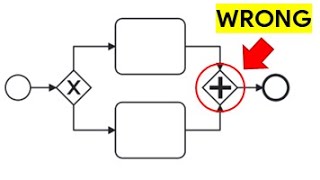
each pool should be labeled according to the entity it represents and each swim Lane should be labeled with the actor's role to create a boundary around the activities they perform now let's look at some key bpmn rules first a start event must not have an incoming sequence flow an end event must not have an outgoing sequence flow two end events in a process must not have the same name if the activities meet at the same endpoint then merge them two activities in a process must not have the same name if the activity occurs multiple times
it should be demonstrated through the sequence flow lines flow objects outside of end events must have an outgoing flow activities must be labeled with a meaningful verb noun phrase a splitting Gateway must have at least two outgoing flows these flows need to be labeled to indicate the conditions that determine the flow a joining Gateway must have at least two input flows data flow objects must not connect to activities through sequence flow lines these objects should be floating and connect to the activities with Association lines message flows must be used for the interaction amongst different pools
all right now let's look at some common best practices for bpmn diagramming first you start and end events to represent the process start and completion and to fit the process model on one page the primary scenario or happy path of the process should be very clear use gateways to depict splitting or merging sequence flows distinguish each exception to the process with Gateway decisions use message flows consistently especially with collaborative diagrams make the process logic clear by labeling the elements consistently and finally keep formatting simple and consistent now let's take a look at an example bpmn
model using a loan underwriting process in this example we'll be looking at a collaborative diagram which involves two separate organizations a mortgage company and a broker firm we can see that the mortgage company has two roles of loan setup rep and underwriter each in its own lane the broker firm only has one swim Lane for the loan officer role now we can see that the process has a clear start and a clear end both demonstrated with the message marker which indicates that a notice both initiates and completes the process as we can see the first
activity is where the setup rep reviews the loan submission then they're faced with a decision of whether or not the file is complete if not the setup rep adds preconditions and sends them to the loan officer to review the preconditions and resubmit the loan notice that message flow lines are used to illustrate the communication between the loan setup rep and the loan officer this is because they're in different pools and you can't use sequence flow lines when the participants are not in the same pool now if the file is complete the setup rep submits the
loan to underwriting where the underwriter will underwrite the loan as you can see the underwrite loan activity is represented as a sub-process this is because underwriting can be pretty involved and could have a number of different subsections such as checking credit reviewing the appraisal reviewing financial statements and assets and so on moving on the underwriter will determine whether or not the underwriting can be completed if no the underwriter adds underwriting conditions and sends them to the loan officer to review and resubmit the loan as you can see here the ad underwriting conditions creates an output
or a data object the data object is floating because it is not part of the sequence if the data object is also an input to a task that follows it can be connected by an association line but you would not connect a data object to an activity with a sequence or message line now if the underwriter is able to complete the underwrite then the underwriter will make a final underwriting decision and the decision notice will get sent to the loan officer and this is where the process ends notice in my annotation that the decision notice
May either be an approval notice or denial notice but because the determination didn't impact the flow of work there was not a need for an additional decision here well folks that's what you need for a clear and effective process model with bpmn if you learned something new be sure to like and share the video and also I'd love to hear your feedback in the comments and be sure to check out all the business analysis and Bes certification training and resources we have for you at the vadoc.com now thank you so much for watching have a
productive and prosperous day and I'll see you next time bye now
Related Videos
![Data Flow Diagram EXAMPLE [How to Create Data Flow Diagrams]](https://img.youtube.com/vi/ab1DZ6o7QBs/mqdefault.jpg)
19:11
Data Flow Diagram EXAMPLE [How to Create D...
The Business Analysis Doctor - IIBA Certification
104,667 views

35:36
LucidChart Tutorial For Beginners (2024) |...
G Force North
4,864 views
![[TUTORIAL] BPMN.IO - Ferramenta Gratuita de Mapeamento de Processos](https://img.youtube.com/vi/E1-Bkm7FRlI/mqdefault.jpg)
47:04
[TUTORIAL] BPMN.IO - Ferramenta Gratuita d...
INOVASTART
4,689 views

19:16
The Only BPMN Tutorial You Will Ever Need ...
The Agile Business Analyst
159,114 views

54:43
Creating a Process Map
WVU Industrial Extension
13,705 views

A Peaceful Place 🍃 Chill Morning Lofi 🍃 ...
Lofi Everyday

28:05
Requirements Workshop - JAD Session (Examp...
The Business Analysis Doctor - IIBA Certification
15,584 views

24:35
BPMN Intermediate Events and How to Use Th...
Camunda
179 views

25:00
Introduction to Process Mapping
Paul Deane
205,410 views

1:56:39
BPMN 2.0 in a Nutshell
ProcessMaker
149,551 views

13:16
Business Process Mapping 101 (Step By Step...
Toni Debelic
8,136 views

23:34
Activity Diagram TUTORIAL and EXAMPLE (How...
The Business Analysis Doctor - IIBA Certification
3,433 views

22:06
Why Every Small Business Should Use THIS i...
Layla at ProcessDriven
109,514 views
40:43
All About BPMN In 40 Minutes
The Agile Business Analyst
7,253 views

11:21
Full Video: Trump and Zelensky Get Into Sh...
WSJ News
1,362,155 views

27:45
Trump’s ‘minion’ JD Vance needs to resign ...
Times Radio
398,758 views

2:02:21
Advanced BPMN 2 0 Process Modeling
ProcessMaker
35,642 views

22:16
BPMN Tutorial for Business Analysts: PROVE...
The Agile Business Analyst
958 views

20:10
Fishbone Diagram EXPLAINED - Root Cause An...
The Business Analysis Doctor - IIBA Certification
15,142 views

20:26
Entity Relationship Diagram (ERD) Tutorial...
The Business Analysis Doctor - IIBA Certification
65,528 views