so in this video we're going to be talking about Google's data center Network architecture with all of their services including Google Cloud platform Google's handling a lot of traffic inside their Data Center and their network has evolved significantly over the years so in this video we're going to go over the choices that Google made and how those choices scaled over the course of them expanding their Network so to start off we'll take a look at their initial approach from 2004 which consisted of a bunch of racks of servers and a core switch that connected all
of them to put this very concretely each rack consists of about 40 servers and at the top of that rack of servers there's a switch and that switch is responsible for moving data between each of the servers that are connected to it so putting this switch at the top of each rack allows the servers within that rack to communicate amongst each other but in order for racks to communicate between other racks we need to introduce another layer of switching that can move traffic between those racks for now we're going to assume that this is all
a single layer 2 Network so this means that the core switch and the top of rack switch don't have to worry about IP packets they only have to worry about ethernet frames so the switch's job is to take Network traffic the comes into it and then figure out based on the destination Mac address which Port the data should come out of on that switch if you're Rusty on some of these networking topics be sure to check out our networking fundamentals video on interview pen.com all right so we were actually oversimplifying our core switch a little
bit Google at this time actually used four core switches and each top of rack switch connected to every single one of the core switches so again each top of rack switch connects to all four core switches and each core switch connects to every single top of rack switch in the cluster in comparison with our sing single core switch approach this does a couple of things first of all it creates redundancy so we don't have to worry as much about a core switch failing because we have three other core switches that we can use to switch
traffic between these top of R switches this also increases our bandwidth by a factor of four so let's say I want to send traffic between these two top of rack switches and each one of these lines can support 1 gbit per second if I have one core switch all I can do is send traffic at 1 gbit per second through that core switch and to the other top of rack switch however if I have four core switches I can send 1 gbit per second through one core switch 1 gbit through per second through the second
1 gbit per second through the third and 1 gbit per second through the 4th for a total of 4 gbits per second going between those two top of rack switches so now let's take a look at how this solution scales at the time this architecture was limited by the size of these core switches so each core switch has to connect to every single top of rack switch and the largest switches available at the time were 512 Port 1 gabit switches so this means that since there's 500 ports on the core switch we can only have
512 server racks in our cluster and the bandwidth associated with that is limited to the number of core switches we have so with four core switches we have 4 gbits of bandwidth for each rack each top of rack switch was a 48 Port 1 gbit switch so four of those 1 gbit ports were connecting to the core switches and another 40 of those ports were connecting to servers four of the ports were unused so with 40 servers in each rack and four gigabits per second for each rack each server only has 100 megabits per second
of bandwidth across the cluster however servers within the same rack can access each other at 1 gbit per second so Google's approach here was to put applications that are really bandwidth intensive under the same rack of servers so communication within that application would be really fast and done through this single top of rack switch and then any data that needs to go across the cluster can go through these core switches however this solution doesn't always work a really good example here is distributed storage so if we have an extremely large scale storage system in our
data center we want to spread that storage system across multiple fault domains so a rack is a fault domain because if power goes down for one rack that problem might not affect other racks furthermore a row of server racks is also a fault domain because a number of racks in a row might be connected to one power circuit the result of this is that we want to distribute our storage across the cluster so in a simple example we'd have one storage server on every single rack in the data center and that limits the scope of
the problem to our storage system as a whole if one rack goes down or even one row of racks goes down however it also means that servers in one rack are going to be frequently accessing data that isn't local to that rack for example let's consider this one server here and let's assume that it has storage distributed across all of these storage servers if we have 512 racks 99% of traffic is going to be sent across the cluster to different racks through these core switches exing storage is actually 50% of the bandwidth used in Google's
data center so these core switches simply don't have enough bandwidth to support this use case so the only way to fix this with the current approach since we're limited by the size of these switches is to Simply add more core switches however this would be a wiring nightmare if we wanted to 10x the bandwidth in our system we'd need 40 core switches and every single one of these top of rack switches would have to be connected to 40 different switches meaning 40 different cables time 512 racks that's a lot of cables so the way to
make this scale is to add another layer to the network so now instead of having a single core switch Layer we have a spine layer and an aggregation layer and instead of using those 512 Port 1 gbit switches we're now using 32 Port 10 GB switches that are designed custom by Google at the time 32 port 10 GB switches were not very common and Google actually used custom line cards with eight ports each and wired those line cards externally in such a way that it created logically a 32 Port 10 GB switch if you want
to learn more about how Google designed this topology you can read more about it in the paper Linked In the description so if we want 10 gbits of bandwidth for each top of rack switch here all we have to do is wire a 10 gbit cable between the top of rack switch and this aggregation switch and with 32 ports on the aggregation switch we can connect to 16 topof rack switches and 16 spine switches and then consequently our spine switches with their 32 ports can handle connecting to 32 aggregation switches so in this topology we
have 512 server racks aggregated down to 32 aggregation switches and each one of those aggregation switches are connected to each of the 16 spine switches by using this architecture here where we have our aggregation switches connected to every spine switch and likewise our spine switches connected to every aggregation switch we enable an architecture that has uniform bandwidth across the cluster so with our 10 G git link between our top of rack switch and our aggregation switch we have 10 gbits of bandwidth between top of rack switches on the same aggregation switch and even at maximum
capacity of every single rack of servers we will still always have some path where we can send data through some spine switch and get full bandwith to any other aggregation switch to do this with our previous architecture using 1 GB core switches we would have needed 40 core switches to manage all of this bandwidth and each top of rack switch would have to be connected to all 40 of those with this new architecture each top of rack switch is only connected to a single aggregation switch simplifying the wiring greatly now one problem we have here
is that we have a single point of failure if our top of rack switch is only connected to a single aggregation switch and that wire fails we have no fallback link and all the servers within that rack will lose connectivity so the solution here was to Simply double the network and create another set of aggregation switches and another set of spine switches and that Network would also be connected to those same topof rack switches so now each rack of servers has link redundancy because it has two links to two different aggregation switches and even if
an aggregation switch fails we'll still have connectivity through the other aggregation switch so the final result of this topology is that we have 32 spine switches 64 aggregation switches and 512 top of rack switches and we can have 20 servers per rack each with an average bandwidth of 1 gbit per second and what's great about this architecture is that we have 1 gbit per second between servers in the same rack and 1 gbit per second between servers in other racks even at Peak bandwidth usage of all servers in the cluster so before this was able
to go into produ uction Google actually went through a completely new version of the hardware that they used for the switches based on lessons they had learned from the original design furthermore the aggregation layer was changed a bit to make the handling of Link failures a bit better so we can think of each top of rack switch as having a left link connecting to this first aggregation switch and a right link connecting to the second aggregation switch if the left link connecting one top of rack switch fails and the right link connecting another top of
rack switch fails at the same time those two switches can't communicate with each other at all even though both of those switches can access other devices in the Network they can't access each other because the left side and the right side switches don't have any way to connect to each other so at the second iteration of this design the two aggregation switches were merged into one by building what is effectively a 64 Port 10 gbit switch this solution still supports 512 racks of 20 servers but each top of rack switch just has two redundant links
to the same aggregation switch now this might seem like we have a single point of failure with this aggregation switch but with the way that this switch was actually designed it consisted of multiple line cards across multiple chassis that were wired externally so even if one of the chassis consisting of half of the line cards in this switch were to fail the switch would still be able to function with half of its ports available one more change was made in this revision and that's that it could support 40 servers for each top of rack switch
instead of just 20 so to do this the top of rack switch was changed from a 24 Port 1 gig switch to a 48 P 1 gig switch with four 10 GB uplinks connecting to the aggregation switch these two extra 10 GB ports were used to connect pairs of topof rack switches together so this means that these 40 servers within this one rack could actually burst to using 20 gbits per second to the aggregation switch and also 20 gbits per second through the other top of rack switch connected to it so if one rack needed
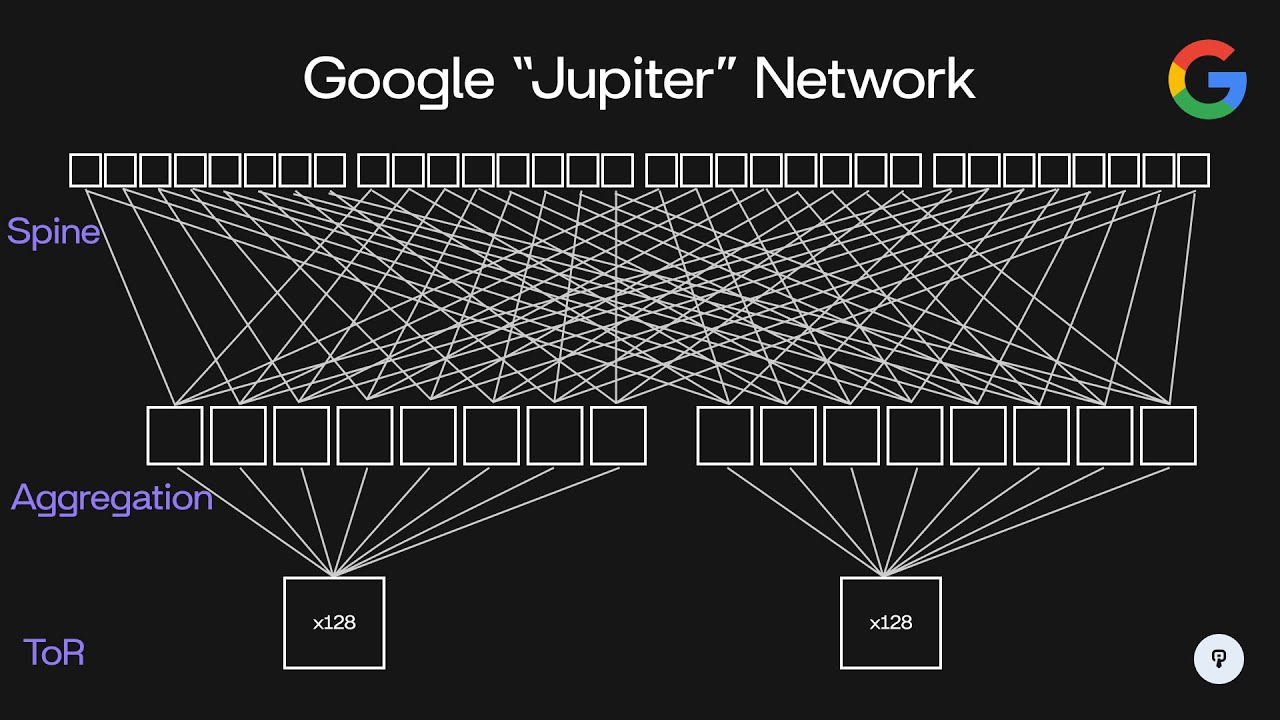
to use more bandwidth for a short period of time it could actually burst up to 40 gbits per second of traffic even though the average bandwidth for that rack would be 20 GBS per second throughout the years Google has evolved this architecture in the same manner to support higher speed higher density switches so nowadays Google's data center network is code named Jupiter and it looks something like this so we have 200 56 spine switches 512 aggregation switches and 8,192 racks supported instead of servers having one gigb connections they now have 10 GB connections to a
top of rack switch and each top of rack switch supports up to 48 servers in each rack the other 16 10 gbit ports on this top of rack switch are used to connect to eight separate aggregation switches connecting to each one using a dual redundant 10 gbit link so this means that two cables are run between this top of rack switch and each of the aggregation switches each set of eight aggregation switches can support up to 128 racks of servers now each of these aggregation switches supports 64 40 gbit uplinks so each of these aggregation
switches is configured to connect to 32 out of these 256 spine switches again using redundant 40 gbit connections to each one so clearly the size of this network has increased dramatically over the course of its expansion going from 10 terabits per second in the initial design to 1.3 pbits per second in this design throughout this Evolution another challenge that Google had to consider was routing across this network so if we consider traffic flowing between this aggregation switch and this aggregation switch that traffic can actually flow through 32 separate spine switches so in this example here
we have pictured this spine switch that connects these two this spine switch this spine switch and this fourth spine switch here and again with 256 total this means that we have 32 Paths of spine switches between any two aggregation switches so the switch has to decide how to load balance traffic between all 32 of those connections and it also has to make make sure that it's aware of when one of those connections goes down in the case of a link failure or switch failure so traditional routing protocols like OPF or Isis transfer link State updates
between independent switches so two switches with traffic flowing between them will connect to each other using OSF for example and they'll send keep Alives and let each other know when a link goes down on one of them then each switch is able to calculate which paths it can use to Route traffic based on which of its neighboring switches are available at the size of Google's data center this type of routing protocol might not make sense Google has a huge number of switches in their Data Center and a huge number of paths between any two locations
so the overhead of this protocol might be too much the nice thing here is that Google's data center network is uniquely static once the network has been designed each switch plays a very specific role in the network and the entire topology of the cluster can be defined in software so Google chose to store that state about the topology of the network centrally in this fir path master and that service communicates the network topology down to these switches the switches then communicate back any link State updates such as when an interface goes down and those link
State updates are communicated to any switches in the network even though data about the network topology is stored centrally switches still make independent routing decisions based on the link State updates that it gets from firepath and this allows for really fast convergence because if one link goes down on one switch that switch can immediately start looking for another path through the network topology to get the data where it needs to go Google's made a ton of really interesting Innovations to scale their data center Network and if you're curious to learn more about them you should
definitely check out Google's paper Linked In the description if you enjoyed this video you can find more content like this on interview pen.com we have tons of more in-depth system design and data structures and algorithms content for any skill level along with a full coding environment and an AI teaching assistant you can also join our Discord where we're always available to answer any questions you might have if you are a friend wants to master the fundamentals of software engineering check us out at interview pen.com