Railway power lines | The Art of keeping them STRAIGHT
3.99M views1078 WordsCopy TextShare
Lesics
Whenever you travel in a train you might have seen these hanging weights near the poles and a strang...
Video Transcript:
whenever you travel in a train you might have seen these hanging weights near the poles and a strange connection of wires near to them what exactly are they why couldn't they just use a simple conductive wire arrangement similar to the normal power transmission system let's explore this topic in this simple case both ends of the wire are fixed as shown temperature variations will cause big problems in this design in the summer time as the temperature increases the material will expand since the ends are fixed this will result in sagging of the wire and sagging wires
are free to deform due to this the wire will go for a wave kind of movement there is a chance of sparks being produced and the pantograph may even get stuck maybe you can tighten these wires too much so that you can reduce the sagging in the summer however this wire will break during the cold winter months as the material contracts now it is clear why fixing a wire at both ends is not a good idea an ideal overhead equipment setup should always keep the contact wire perfectly straight without breaking the wire let's see how
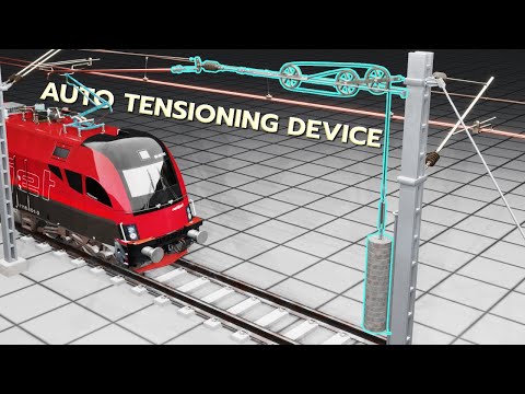
we can achieve this first we must design a simple system to take care of this expansion and contraction problem in this design we are replacing a fixed connection with a pulley when you attach a dead weight to this free end the wire sag will be greatly reduced here tension in the wire is the same as the weight of the discs this arrangement will compensate for any temperature change the more the temperature increases the more the weight will pull down with this pulley and weight arrangement can we increase the distance between the poles to any extent
the answer is no although the concrete weights reduce the sag of the wire they can never completely eliminate the sag especially when the span is too large even with a good amount of disc weight the sag will be considerable here is an easy experiment to prove it this experimental rig is exactly same as og system one and the cable is fixed here and other end is passing over a pulley you can see a good sag let's add a weight and see what happened to the system [Music] the size has decreased now let's add one more
weight a really heavy weight the stock has decreased again but not zero this means that if you want a perfect straight line here you have to have an infinite amount of weight at the pulley side due to this the maximum distance allowed between the poles is around 50 meters the solution is simple introduce more support in between here's the trick you can see an extended cantilever in these supports they should be able to swing as shown such that when the temperature variations occur they will not block the movement of the wire however the last cantilever
is fixed as we saw earlier we've developed a small wire unit or overhead equipment for the electric train now it's time to achieve a long oag system starting from this design the solution is simple just duplicate this entire unit and start this new unit before the first unit ends to maintain the electrical continuity between units a few flexible jumper wires are used you can see how the jumper wires electrically connect the first and second unit we can run our electric train successfully in this system you can see clearly how a pantograph changes contact from one
ohe unit to another we had a successful test run of the train however if you observe carefully you'll notice that the contact wires are still sagging a little bit the disc weight and supports with swing arms could not solve the sag problem completely can you think of a solution to fix this issue once and for all we'll give you one clue the almost perfect straight line can be achieved with the help of one more pulley wire system which is placed slightly above the current contact wire can you spot the solution now it's relatively simple these
two wires have the exact same shape now if you take a connecting wire called a dropper which has the same length as the distance between the wires nothing will happen to their shape however what would happen if we connected the wires using a dropper of a shorter length this shorter dropper will obviously pull the contact wire up while pulling the upper wire down in short the sag of the upper wire will increase while the bottom wire will have a perfect zero sag at this point the upper wire is called catenary and the lower wire is
obviously the contact wire by adding more droppers the contact wire will become even straighter these droppers also absorb vibrations arising from the interaction between the pantograph and the contact wire we can simplify this system by attaching the ends of both wires to the common pulley however the tension in the wires must be the same as it was in the earlier design does this mean we need to add more weights obviously this is not a good idea let's implement a clever pulley arrangement that provides an immense mechanical advantage a 2 newton force at the pulley gives
three newtons of tension in each wire as you can see now the contact wire is almost straight with this system the pantograph always remains in contact with the contact wire till now we have seen that the atd is attached at one end and the other end is fixed we saw earlier how to duplicate this simple unit to achieve a long ohe however before duplicating if you mirror this simple design the whole design will be much simpler this is the final ohe design from these visuals you will understand a lot of details about this design catenary
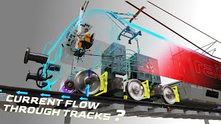
wires are kept at the same voltage as the contact wires otherwise there will be current flow via the droppers and unnecessary energy loss additionally if there is any damage in the contact wire the system will not fail please have a look at this jumper design the jumper is passing through the catenary wire this means the power will be supplied by the catenary wire through jumpers thank you for watching the video see you next time
Related Videos

10:14
The Brilliant Engineering behind Pantographs!
Lesics
2,509,823 views
11:34
The Fastest train ever built | The complet...
Lesics
50,239,637 views

5:31
Why Are There Stones Along Railway Tracks?
Science ABC
9,729,931 views

13:05
The Reason Train Design Changed After 1948
Joe Scott
1,001,205 views

29:46
Longest Trains In The World
BE AMAZED
348,210 views

15:11
How Tesla Reinvented The Electric Motor
The Tesla Space
350,434 views
14:53
Why Are Rails Shaped Like That?
Practical Engineering
2,570,684 views
18:49
Rail Electrification Systems - Learn EVER...
Railways Explained
162,438 views
8:58
The Fascinating Engineering behind Electri...
Lesics
2,808,691 views

15:28
Golden Gate Bridge | The CRAZY Engineering...
Lesics
16,318,753 views

15:57
Why French Trains Are The Fastest
Mustard
3,920,434 views

15:53
Why Railroads Don't Need Expansion Joints
Practical Engineering
3,475,650 views

8:33
The Self Balancing Monorail
Primal Space
8,739,017 views
14:39
The Engineering Marvel called Panama Canal
Lesics
9,968,207 views

9:54
How Wind Turbine Technicians Risk Their Li...
Insider News
2,880,591 views

16:18
Why Locomotives Don't Have Tires
Practical Engineering
1,176,400 views

11:29
Wild Old DIESEL LOCOMOTIVE Engines Cold St...
Sergey322
57,677 views
19:22
Mechanical circuits: electronics without e...
Steve Mould
6,870,086 views

6:06
How do trains change the tracks?
Lesics
12,741,227 views
36:24
How a Steam Locomotive Works (Union Pacifi...
Animagraffs
3,485,591 views