Ethernet Switches and VLANs - Network Link Layer | Computer Networks Ep. 6.4.3 | Kurose & Ross
20.36k views2417 WordsCopy TextShare

Epic Networks Lab
Answering the question: "How do layer-2 switches work?" Discusses MAC learning tables, layer-2 for...
Video Transcript:
in this video we look at layer 2 switches and vlans let's get started [Music] now let's look at switches and specifically we'll be looking at ethernet switches which operate based on ethernet addressing and protocol that we've been looking at in recent videos when we talk about a switch we're referring to a layer 2 device that actively performs storing and forwarding of ethernet frames certainly in the core of the network you may find other layer two protocols and switches associated with those protocols but since ethernet is the device that you're most likely to encounter we'll stick
to discussing ethernet switches so the basic operation is that the switch looks at the destination address of the frame and determines what port or ports the frame should be forwarded to in accessing the links it will be using the csmacd algorithm that's part of ethernet the operation of the switch itself is transparent meaning that the hosts operate as if there's a direct connection between them whether or not there's a switch in the middle at least for the basic functionality switches do not require configuration and can operate in a plug-and-play manner due to their self-learning behavior
here we have an ethernet lan with a switch in the middle the switch has six ports one dedicated to each of the hosts so unlike the ethernet architectures that we talked about before where it was a shared medium that all the hosts were contending for each of these links is a separate collision domain and because there's only two interfaces on each link they can run at full duplex so each of the switch's ports operates using the ethernet protocol independently of all the other ports the switches also perform buffering so just as we saw with the
routing switching plane if there's contention for an outgoing port packets can be buffered temporarily and then transmitted once the port is available and as before we can also have congestion to the point that the buffer will overflow and drop packets when you put all of this together it means that we can have simultaneous flows going on through the switch so in this case we have a transmitting to a prime simultaneously with b transmitting to b prime and there's no contention between these flows they're able to happen simultaneously and each can utilize their full link bandwidth
of course if we have two different hosts transmitting to one host in this case eight a prime and c to a prime they're going to have to share the bandwidth on the link between the switch and a prime so the switch will buffer packets temporarily and interleave them but if the total rate exceeds the bandwidth of the a prime link then the buffer will start to drop packets now we already said that the switch doesn't require any configuration to perform its basic functions so the question is how does it know to forward frames to a
prime out the correct interface we also already said that the switch uses the destination mac addresses and the frames so somehow it has to learn that frames destined to a-prime's mac address need to be forwarded out port 4. and indeed this is what is stored in the switch's forwarding table mac address associated port and a timeout if you remember back to layer 3 routers we had to configure the routing table either manually or using a dynamic routing protocol so how does the layer 2 switch essentially perform the same forwarding function but without this configuration step
in the case of a switch it does not have a routing protocol and does not need to communicate with other switches instead it is able to learn which hosts can be reached through which interface and the process is as follows we have a sending a frame to a prime and at this point we'll say the switch has just started up and it's forwarding table is empty however any time the switch receives a frame it can read the source address and it's just learned what interface it can use to reach that source address so from this
incoming frame it's just learned that a is on interface one but while that information is great for next time it needs to send a frame to a it doesn't help the switch get the frame to a-prime so let's look at what else happens when a frame arrives at a switch as we just saw it records the source mac address and the port that it came in on to populate its forwarding table the mac address is used as the key or index to this table now as we mentioned before there's no structural relationship between the mac
addresses and their position in the network so searching this switch table requires exact matching if it finds a switch table entry for the destination mac address in the frame it then has to check and see if it received this frame on the same interface meaning it won't send the frame back out the same port that it just came in on so as long as the port in the table is not the same ones the frame came in on it will then forward the ethernet frame based on the switch table but what about the case where
the destination mac address is not yet in the switch table in that case the switch will send it out all interfaces and this is where you can see that the behavior drastically diverges from the process of layer 3 forwarding in layer 3 the default behavior is to drop packets that have no matching forwarding record and the reason for this is scalability switches are used in local subnets with relatively small numbers of hosts on each subnet so they can afford to flood a packet to the whole network every now and then to facilitate the process of
learning mac addresses routers on the other hand could not default to this behavior because if they did they would end up forwarding packets to unknown destinations to the entire internet so let's walk through the rest of our example we have a sending a frame to a prime and no entries in the switches forwarding table so far as the frame arrives at the switch it learns from the source field of the frame and populates a's mac address and port number in the forwarding table since a prime is not in the forwarding table it has to fall
back to its default behavior and flood the frame out all of the other interfaces since the frame went out all the ports a prime received it and can respond back so it sends a frame to a via the switch and the switch already knows what interface a lives on so i can selectively send it out that port and it also just learned what interface a prime is on so it can populate its switch table accordingly now any future frames from a to a prime will only need to be sent out the port to a prime
and will no longer need to be flooded so that's the basics of how a switch is able to populate its forwarding table without the destinations being configured the same behavior works even when multiple switches are connected together so now we have one switch with three hosts connected to multiple other switches and this is a common enterprise situation where you might have one switch connecting all the offices in the hallway and all of the hallway switches connected back to a building switch so if i need to get frames from a to g it works in exactly
the same way a will send out the frame to s1 and if it doesn't know what interface g's mac address is on it will flood that out to all the hosts now the flooded frame will get to s4 which will perform the same behavior so if none of the hosts have g's mac address in their table as frame will reach every single host on the entire network so we certainly don't want the flooding process to happen too often because it does consume resources on every link in the network however once g gets a is frame
and replies back every switch along the path will learn what interface to use to get to g and the flooding for use mac address will stop now let's tie this into the bigger picture we have some number of switches connected together and these can use self learning to reach every other host on that layer 2 network and since all of these switches are hanging off one port from the router they must all be part of the same ip subnet so the self learning process stops when it reaches the router unlike a switch the router will
only accept ethernet frames with the router's mac address in the destination field the router will not forward ethernet frames with other destination addresses and so the scope of this flooding self-learning discovery process is confined to a single ip subnet as a reminder let's look at the network stack on each of these devices we have our end hosts running the entire network stack and then we have routers which are layer 3 devices so as a package reverses a router the first layer 2 header is stripped off and the router just forwards to ip datagram and then
it creates a whole new layer 2 frame on the output port however when that frame reaches a switch the switch does not remove the layer 2 header it just makes its forwarding decision based on the existing layer 2 destination address so both of these devices perform forwarding and we even discuss the switching fabric that's inside of a router so the real difference is in the criteria for the forwarding decision routers use routing algorithms to compute forwarding tables based on ip addresses but switches learn layer 2 mac addresses and populate their switch table based on those
now we'll look at vlans which is an enhanced functionality that modifies the way switches work in order to increase flexibility we've mentioned the flooding aspect of the switch mac address learning process and this is clearly a scalability concern anytime you take one packet and flood it to the whole network that's an exponential consumption of resources and we've also seen some other protocols that use broadcast traffic so any packet using the destination broadcast address also gets flooded to the entire switched ethernet subnet one answer to this is to break up the subnet into multiple smaller subnets
and this improves efficiency by reducing the number of hosts that will hear every single flooded frame however this can decrease flexibility if physical wiring has to be changed every time users move around and need to be connected back to a particular switch because it's separated by a router so in this example we have a cs user that's going to have an office physically in the ee department but wants to be on the cs switch so in that sort of environment it's easier to maintain a flat switched lan like we see in this picture and not
have to worry about where a user is physically in that network topology so we have these two competing goals we want to break up our broadcast domain for efficiency but we want one large flat network for convenience vlans are the solution to this we can take one physical switch and divide it up into multiple logical switches for example if we have a switch for a hallway but the users in that follow fall into two different logical groups we don't really want to have to add a separate physical switch and run the associated cabling from a
router to that switch and from that switch to certain offices instead we make a software configuration change on the existing switch and are able to partition the users that way and so that switch is going to operate just like it was two physical switches or more we can have large numbers of vlans configured if need be we also have some flexibility in how this is done we can take physical ports and assign them to vlans or we could assign certain mac addresses to certain vlans so no matter which port that particular computer plugs into it
will always be on the vlan that it's configured to be on now as we mentioned the point of separating this into two logical switches is to increase efficiency by reducing the number of hosts that hear broadcaster flooded messages and that means that these two vlans need to be on separate subnets separated by a router so each of those vlans will need an uplink back to either other switches in their vlan or to a router interface typically we're going to have vlans spanning multiple switches and so in the simplest case to connect these switches we would
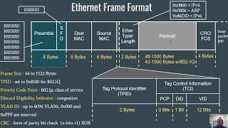
need a link connecting the red vlan and a separate link connecting the blue vlan but that would cause its own scalability issue with the need to run multiple cables in parallel between these devices and extra consumption of switchboards so vlans include the concept of trunk ports frames from multiple vlans can be sent over the trunk port and they have an additional header field that tells the receiver which vlan they belong to this vlan header was not part of the original ethernet specification so it's added in 802.1q a nato 2.1 queue frame takes our original ethernet
frame and adds a couple fields right in front of the type these include the tag protocol identifier the vlan id itself which you see has 12 bits so we can define many different vlans if need be and a three bit priority field that wraps up our discussion of switches and vlans which we might call virtualized switches our next topic is looking at mpls multi-protocol label switching which is a mechanism for virtualizing links see you then we hope you enjoyed this video if you found it to be useful please click the like button to be notified
when more videos are posted for this class please subscribe to our channel and click the bell
Related Videos

4:35
Layer-2.5 MPLS (Multi-Protocol Label Switc...
Epic Networks Lab
10,565 views

12:48
MAC Addresses, ARP, and Ethernet - Network...
Epic Networks Lab
29,153 views

28:06
6.3 Multiple Access links and protocols
JimKurose
66,515 views

6:02
Layer 2 vs Layer 3 Switches
PowerCert Animated Videos
829,520 views

12:26
Wireless & Mobile Link Challenges - Wirele...
Epic Networks Lab
16,881 views

17:26
Media Access Control (MAC) Protocols - Net...
Epic Networks Lab
21,567 views

15:17
802.11 How WiFi Works - Wireless Networks ...
Epic Networks Lab
18,125 views
15:25
The Data Link Layer, MAC Addressing, and t...
danscourses
104,914 views

14:20
3.2 Transport layer multiplexing and demul...
JimKurose
102,449 views

28:38
Network Virtual LANs (VLANs), Explained Si...
Doug Johnson Productions
157,582 views

11:13
6.1 Introduction to the Link Layer
JimKurose
68,394 views

9:11
What is Ethernet?
RealPars
2,176,470 views
18:01
Home Network For Beginners - What You NEED...
Steve DOES
1,288,908 views

14:42
How Mobile IP Works - Wireless Networks | ...
Epic Networks Lab
10,661 views

13:52
Software Defined Networks & OpenFlow - IP ...
Epic Networks Lab
24,274 views

27:02
Master the Basics of Computer Networking i...
KnowledgeCatch
73,773 views

22:21
04 - Network Switches & Ethernet - Home Ne...
Crosstalk Solutions
188,768 views

19:04
1.3 The network core
JimKurose
136,445 views