Gas Turbine | Gas Turbine Working | Gas Turbine Components | Gas Turbine Overhauling
2.13M views6601 WordsCopy TextShare
Oil Gas World
#Oilgasworld #Oilandgaslearning
Gas Turbine Working and Components. Details about Major Components.
...
Video Transcript:
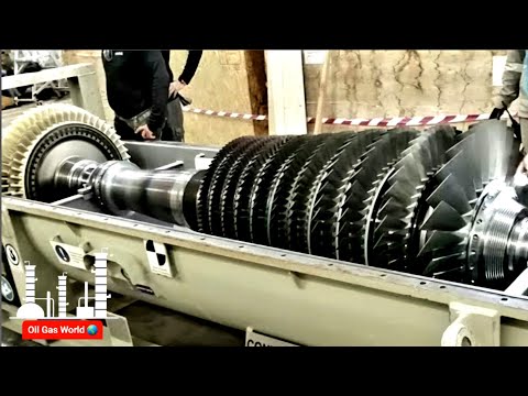
ms-9001e gas turbine training this video will describe the main components of the gas turbine and its functional description this gas turbine is also known as pg9171e downstream the shaft of this gas turbine rotates at 3000 rpm counterclockwise as viewed looking downstream this gas turbine consists of the following main components the compressor the combustion system the turbine the exhaust assembly the bearings the compressor is a 17 stages axial flow compressor with variable inlet guide vanes air is compressed to a pressure ratio of 12 to 1. each stage consists of a set of rotating blades and set
of stator stationary blades compression is achieved in each stage as the rotating blades increase the relative velocity of the air then the stator stationary blades convert the gained kinetic energy into a pressure rise and guide air to enter the following stage at the proper angle the compressor consists of two major components the compressor rotor and the compressor stator the compressor rotor has 17 stages of rotating blades it is assembled of 15 individual wheels and two stub shafts all wheels are held together with 16 tie bolts and nuts the forward stub shaft is machined to provide
the following features thrust collar which carries the axial downstream and upstream thrust forces to prevent rotor axial movements journal surface for bearing number one and surfaces for oil and air seals forward balancing groove to add balancing weights for vibration control forward flange to connect the gas turbine shaft to the auxiliary gearbox a speed ring with 60 teeth is attached to the forward flange for speed measurements and protection the aft stub shaft is machined to provide the following features a fan is machined on the forward side of the stub shaft this fan draws air through the
gap between the 16th wheel and the aft stub shaft to cool the turbine rotor parts aft balancing groove aft flange to connect the compressor rotor to the turbine rotor labyrinth teeth to mate with compressor stator parts to prevent compressor discharge air from escaping inside the inner barrel around bearing number two the compressor rotor blades are airfoil shaped and are attached to the wheels by means of dovetail arrangement the first wheel blades are mounted on the wheel portion of the forward stub shaft and they have only aft spacers while the next 15 wheel blades have forward
and aft spacers the 17th stage blades are mounted on the wheel portion of the aft stub shaft and they have only forward spacers these spacers are placed to maintain the relative position between the rotor and the stator blades rotor blades are held in axial position by staking at a blue painted section lit casing to prevent suction of contaminants into the compressor variable inlet guide vanes are located at the aft end of the inlet casing the function of these guide vanes is to control the amount of airflow across the compressor the total number of the inlet
guide vanes is 64 blades each blade stem is inserted into a hole machined on the inlet casing each four of them are supported from below by one inner segment a pinion gear is installed to each blade stem and is keyed into position these pinions are rotated by a ring gear which is assembled to the control ring the control ring is positioned by a hydraulic actuator to obtain the desired inlet guide vanes opening angle the opening angle for this gas turbine ranges from 34 to 84 degrees the forward casing contains the first four compressor stator vanes
the lower half is equipped with two trunnions used with other trunnions on the turbine shell to lift the gas turbine to or off the turbine base it also features a mounting point for the forward turbine support plate the aft casing contains the 5th to the 10th compressor stator vanes a groove is machined at the forward face around the fifth wheel blades where air is extracted for cooling and sealing functions through two ports in the upper half and two on the lower half another groove is machined around the 11th wheel blades where air is extracted for
surge protection during transient operation the discharge casing is the final portion of the compressor casings being the largest single casting it is the keystone of the gas turbine structure it connects the compressor to the turbine section and supports the combustion system the discharge casing contains the last seven stages of compressor vanes and two rows of exit guide vanes the discharge casing consists of outer and inner cylinders these inner and outer cylinders are connected by means of 12 struts these struts flare out to meet the large diameter of the turbine shell while providing spacing for transition
pieces in between the inner cylinder is extended to the forward side by the inner barrel the inner and outer cylinders of the discharge casing form the compressor diffuser which converts some of the kinetic energy of the compressed air into a pressure rise at the forward end of the inner barrel a honeycomb seal is installed to mate with the labyrinth teeth on the aft stub shaft a brush seal is running against the rotor's smooth surface this arrangement is also known as the high pressure packing the function of this arrangement is to control the amount of compressed
air leakage inside the inner barrel this air despite being used to cool the first forward wheel space the amount should be minimized to improve unit efficiency and minimize air leakage inside bearing two seals the lower half of the inner cylinder supports the bearing number two and provides the opening for the lube oil supply and drain piping the upper half of the inner cylinder has an opening for the vent pipe seals are installed at these openings to prevent compressed air from escaping inside the inner cylinder the discharge casing also supports the turbine first stage nozzles the
first stage nozzle support ring is mounted on the aft end of the inner cylinder the stationary vanes of the compressor are also airfoil shaped the blades of the first eight stages are mounted by dovetail arrangement to ring segments these ring segments are inserted into circumferential grooves on the casing the blades of the last nine stages have a square base dovetail and are inserted directly into the circumferential grooves on the casing two rows of exit guide vanes are located at the end of the compressor these stationary veins help in reducing the rotation of the airflow and
increasing the pressure the combustion system of this gas turbine is a reverse flow type with 14 dln1 can annular combustion chambers arranged around the periphery of the compressor discharge casing combustion chambers are numbered counterclockwise as viewed looking downstream starting from the vertical center line with dual fuel capability this turbine burns either gas fuel or liquid fuel in this section the pressurized compressor discharge air is directed upstream to enter the combustion zone mixed and burned with fuel producing hot gases which will drive the turbine the combustion system main components are the combustion wrapper combustion can cover
fuel nozzle secondary fuel nozzle the liner flow sleeve transition pieces crossfire tubes spark plugs flame detectors the combustion wrapper is a fabricated horizontally split casing that encloses the combustion system it provides a supporting surface for combustion chamber assemblies the wrapper forms a large plenum which receives the compressor discharge air this air is directed upstream to the combustion chambers the forward face of the wrapper is slanted at 13 degrees angle from the vertical and contains machined openings to mount the 14 combustion chamber covers the wrapper is supported by the compressor discharge casing and the turbine shell
the combustion chamber cover function is to carry the combustion chamber components the flow sleeve is mounted on the combustion chamber cover the flow sleeve forces the air to move upstream forming a uniform air jacket around the liner for precise combustion and cooling functions among the 14 chambers the liner is the core of the combustion system inside the liner air and fuel are mixed and burned providing hot gases the liner is mounted on the flow sleeve at the forward side by three liner stops and supported at the aft by inserting the liner inside the transition piece
this configuration allows thermal expansion of the liner spring seals located at the aft end of the liner to prevent the compressor discharge air from leaking into the hot gas path the liner consists of the liner body multi-nozzle cap assembly and the venturi these parts are assembled together by rivets combustion air flows into the liner through various locations primary combustion air flows through the primary gas tips air enters for metering holes for combustion functions secondary combustion air enter through the center body dilution air enters the liners from three holes at the aft side of the liner
due to the extremely high temperatures encountered inside the liner all surfaces which are exposed to the flame are protected by thermal barrier coating the combustion liner is also protected by film cooling as air flows through the liner cooling rings to make an air film adjacent to the liner surface this air film keeps the hot gases away from the liner metal the liner cap is protected by film cooling and backside impingement cooling the venturi is cooled by backside impingement cooling all combustion chambers are interconnected by means of crossfire tubes these tubes enable flame to propagate from
one chamber to another crossfire tubes are couples of male and female parts each is inserted into the liner crossfire tube collar and held on position to the bracket on the flow sleeve by the crossfire tube retainer all crossfire tubes are surrounded by crossfire outer tubes these tubes connect the combustion chamber outer covers together packing is installed to minimize leakage and held by flanges on both sides of each tube outer tubes are prevented from sliding by split retainers mounted on the flanges as the dln1 system features two combustion zones fuel is injected to the combustion chambers
through the primary and the secondary nozzles the primary fuel nozzle is functionally integrated with the combustion chamber end cover and provides a flange in the center for secondary nozzle mounting fuel is injected into the liner primary zone through six identical nozzles gas fuel enters the primary nozzles assembly through the fuel gas connection flange and is routed through internal machined passages to the orifices located in the gas tips atomizing air is introduced in the same manner through internal passages and exits to the primary zone through multiple holes on each of the gas tips water is supplied
to the primary water injection manifold then distributed to the six nozzles through piping to each one of the fuel oil flange and tip assemblies liquid fuel is supplied to a liquid fuel distribution valve to equally distribute the fuel across the six nozzles especially on startup fuel flows through piping to the primary zone through the liquid fuel tip located at the center of the gas tip the secondary nozzle features a supply flange for secondary gas fuel which is injected into the secondary premix zone through multiple holes a small amount of the secondary gas is injected after
the secondary swirler this amount is called the secondary gas subpilot this amount of gas promotes the secondary flame stability transfer gas for transient transfer operation is supplied to the relevant supply flange and is injected before the secondary swirler also liquid fuel and water flow from the inlet flanges to the combustion zone where they are injected at the aft tip of the secondary nozzle assembly combustion is initiated by means of two spark plugs mounted on the 11th and 12th combustion chambers the spark plug is mounted on the spark plug ball joint this joint allows adjustment of
the spark plug relative to the liner on a dln1 combustion system spark plugs remain inside the liner throughout all the operation for startup and primary zone reignition functions once the flame is started on these chambers it propagates to the other chambers through the crossfire tubes flame is detected on combustion chambers by means of ultraviolet flame detectors mounted on four chambers the 14th the first the second and the third combustion chambers as the dln system features two combustion zones flame is detected by four flame detectors in each zone the flame in the primary zone is detected
by flame detectors mounted on pads on the combustion chamber cover this detector is inclined to detect the flame through one of the metering holes around the liner body secondary flame detectors are mounted on the secondary nozzle flame flange flame is detected in the secondary zone through a viewport in the secondary swirler transition pieces are the interface between the combustion and the turbine sections they direct the hot gases from the liners to the turbine first stage nozzles the first stage nozzle entrance area is divided into 14 equal areas receiving the hot gas flow due to the
extremely high temperatures of the passing hot gases the inside surface of the transition piece are coated with thermal barrier coating cooling air is introduced by allowing compressor discharge air through the vent plate to the cooling holes machined on the transition piece aft end the transition pieces are sealed to both outer and inner side walls of the first stage nozzle by the outer and inner seals these seals are inserted into grooves on the first stage nozzle to minimize compressor discharge air leakage into the hot gas path the sides of the transition pieces are sealed by side
seals side seals are held in position by side seal retainer blocks these blocks are mounted on the first stage nozzle retainer ring transition pieces are supported at the aft side by means of the aft mounting bracket which is mounted on the first stage nozzle retainer ring each transition piece is supported at the forward side by a support clamp this support clamp is mounted on the compressor discharge casing the turbine section consists of three stages each stage consists of a set of stationary nozzles followed by a set of rotating blades the stator nozzles convert the energy
in the hot gases leaving the combustion system into kinetic energy and direct the gases at the proper angle to rotate the moving blades to produce the mechanical rotational energy the turbine section consists of the turbine stator the turbine rotor the turbine stator consists of the following parts the turbine shell the shrouds the nozzles the turbine shell function is to control the radial and axial positions of the shrouds and the nozzles and the relative clearances between the nozzles and the rotating buckets the position of these parts is critical to the turbine performance the lower half features
two trunnions used with other trunnions on the forward compressor casing to lift the gas turbine to or off the turbine base the external surface of the turbine shell incorporates cooling passages unlike the compressor blades the turbine rotating bucket tips don't run directly against the stator casing but against curved segments called the shrouds the primary function of the shroud is to minimize the tip leakage these shrouds are attached to the turbine shell by sliding onto the t-hook arrangement machined on the turbine shell joints between first stage shrouds are sealed by cloth seals shrouds are maintained in
the circumferential position by radial pins from the turbine shell the first stage shroud is coated with thermal barrier coating to withstand the extremely high temperatures at this stage the second and third stage shrouds have teeth that mate with teeth on the tip of the second and third stage buckets this labyrinth seal minimizes tip leakage for better tip clearance a honeycomb seal is integrated on the second and third stage shrouds this honeycomb is relatively soft material the cutter teeth on the tip of the second and the third stage buckets open a slot on the honeycomb seal
without any material transferred providing tighter clearances to improve the unit efficiency shrouds of the last two stages are sealed by interconnecting tongues and grooves and by key seals in the first stage nozzles hot gases received from the combustion system are expanded and directed to the first stage rotor buckets the first stage nozzle consists of 18 cast nozzle segments each segment contains two airfoil partitions these partitions are hollow this permits the relatively cool compressor discharge air to cool the nozzle segments by entering from the impingement plates and exiting through holes on the trailing edge into the
hot gas path the 18 segments are contained on a horizontally split retaining ring the retaining ring is supported to the lower turbine shell by two lugs extruding from the lower retaining ring half and held in place by clamps the retaining ring is centered by two eccentric pins from the turbine shell this configuration permits radial expansion due to the high temperatures encountered while the ring remains centered to the shell the aft outer face of the retaining ring is loaded against the forward face of the first stage shroud with seal strips in between to prevent compressor discharge
air leakage between the nozzle and the shell the nozzle one assembly is prevented from moving forward by four lugs extruding from the outside diameter of the retaining ring at 45 degrees from vertical and horizontal center lines these logs fit in a groove machined on the turbine shell on the inner side wall the nozzle is sealed and supported by direct bearing of the nozzle inner load rail against the first stage nozzle support ring the first stage nozzle support ring is mounted on the aft face of the compressor discharge inner cylinder hot gases leaving the first stage
rotating buckets are expanded again and directed to the second stage rotating buckets by the second stage nozzle the second stage nozzle set consists of 16 segments each segment contains three airfoil partitions the nozzle segments are assembled by fitting the male hooks on the forward and aft sides of the outer side wall into the female groove on the aft side of the first stage shroud and on the groove on the forward side of the second stage shroud seals are installed between the segments to minimize leakage the nozzle segments are held on the circumferential position by radial
pins from the turbine shell into axial slots on the nozzle outer side walls annular curved segments are attached to the inner side wall of the nozzle these segments are called the diaphragms each diaphragm is secured to the nozzle by a pin these diaphragm segments prevent hot gases leakage past the inner side wall of the nozzle and the rotor a high low labyrinth seal is machined on the diaphragm inside diameter these seals mate with opposite ceiling lands on the turbine rotor spacer the second stage nozzle is cooled by compressor discharge air passing through the first stage
shroud some of this air exits through holes on the airfoils trailing edges the remainder of the cooling air is directed to the first stage half wheel space through three cooling air tubes assembled on the diaphragm a brushed seal segment is installed on the inside diameter of the diaphragm between the labyrinth seals this brush seal is in continuous contact with the turbine rotor spacer surface to control the amount of the cooling air passing from the first stage aft wheel space to the second stage forward wheel space this ensures more precise cooling and better unit efficiency the
third stage nozzle receives the hot gases from the second stage rotor buckets expands it further and directs this flow to the third stage rotor buckets the third stage nozzle set consists of 16 segments each segment contains four airfoil partitions a diaphragm segment is also attached to the inner side wall of the nozzle the third stage nozzles are not air cooled these segments are installed to the stator in the same manner of the second stage nozzle the third stage nozzle is supported by the second and third stage shrouds the nozzle segments are held on the circumferential
position by radio pins from the turbine shell into axial slots on the nozzle outer side walls the turbine rotor consists of the forward wheel shaft first second and third stage turbine wheels two turbine wheel spacers the aft wheel shaft all parts are assembled together by 12 studs the forward wheel shaft is machined to provide the following features journal surface for bearing number two and surfaces for oil and air seals forward balancing groove forward flange to connect the turbine rotor to the compressor rotor the forward wheel shaft is hollow to pass the turbine rotor cooling air
the first wheel carries the 92 buckets of the first turbine stage like the next two stages buckets could be disassembled without rotor removal being the first part that encountered by the hot gases leaving the first stage nozzles these buckets are protected by thermal barrier coating from outside and air cooled from inside when the bucket is attached to the wheel a small air plenum is formed in between the rotor internal cooling air which passes through slots on the forward face of the first wheel spacer is fed into these plenums cooling airflow from this plenum to a
series of longitudinal air passages to cool the bucket and exit at the recessed bucket tip buckets are attached to the wheel by straight axial entry multiple tang dovetails that fit into matching cutouts on the wheel rims the buckets are prevented from moving axially by the d key arrangement a radial locking pin is installed before the first bucket then the first bucket is installed and locked in place by the d key this is repeated for the next 90 buckets the last bucket is installed and an axial locking pin is inserted on the locking bucket dovetail this
pin pushes the radial locking pin to hold the last bucket on position the first wheel spacer is located between the first and second turbine wheels spacer function is to define the axial position of the turbine wheels the outer diameter of the spacer carries the diaphragm ceiling lands slots are machined on both forward and aft faces for cooling functions the second wheel carries the buckets of the second turbine stage 92 buckets are also installed on the second wheel buckets are attached to the wheel by the same dovetail arrangement of the first stage but they are held
on the axial direction by twist locks arrangement twist locks are first placed on the wheel then buckets are installed as a 360 degrees ring due to the interlocking between the buckets once the buckets become on position the twist locks are rotated and stacked buckets are internally cooled by the rotor internal cooling air which passes through slots on the aft face of the first wheel spacer this air is fed into a plenum casted on the bucket shank from this plenum air flows into spanish holes machined on the bucket and exits at the bucket tip the second
stage bucket tip is enclosed by a shroud which is a part of the tip seal these shrouds interlock from bucket to bucket to provide vibration damping these shrouds also feature the cutter teeth which open slot on the honeycomb seal and mates with the seals on the shroud block the second wheel spacer is located between the second and third turbine wheels slots are machined on the forward face the forward face of the spacer is machined to form a gap at the mating surface with the second stage wheel for cooling functions the third wheel carries the buckets
of the third turbine stage 92 buckets are also installed on the third wheel third stage buckets are not internally cooled third stage bucket tip is also enclosed by a shroud buckets are attached to the wheel by the dovetail arrangement and held on the axial direction by twist locks arrangement like the second stage the aft wheel shaft is machined to provide the following features journal surface for bearing number three and surfaces for oil and air seals aft balancing groove aft flange to connect the turbine rotor to the generator rotor the turbine rotor must be maintained at
reasonable operating temperature to assure a longer turbine service life for this purpose bucket veins are not directly attached to the dovetail instead they are connected to their dovetails by means of shanks these shanks locate the bucket to wheel attachment at a significant distance from the hot gases combined with the diaphragm segments this arrangement isolates the rotor away from the hot gases flow seals from the first stage nozzle support ring mate with ceiling wings extruding from the forward side of the first stage bucket shank also seals from both sides of each diaphragm mate with ceiling wings
from both sides of each bucket the seal from the exhaust frame mates with the ceiling wing on the aft side of the third stage bucket at the forward end of the inner barrel the first stage aft wheel space is cooled by the compressor discharge air supplied through the second stage nozzle the second stage forward wheel space is cooled by a portion of the first stage half wheel space cooling air which passes through the labyrinth and brush seal the second stage aft wheel space is cooled by the rotor internal cooling air which passes through the slots
on the forward face of the second wheel spacer the third stage forward wheel space is cooled by a portion of the second stage aft wheel space cooling air which passes through the labyrinth seal the third stage aft wheel space obtains the cooling air from the exhaust frame cooling system the rotor internal extraction cooling air is utilized for bucket and wheel space cooling this airflow also maintains the parts of the rotor at approximately compressor discharge temperature this ensures longer service life for turbine rotor parts for efficient gas turbine operation clearances between all rotating and stator parts
should be tight as possible as the turbine shell controls the radial and axial position of all turbine stator parts the shell should be isolated from the high temperature of the enclosed hot gases this will ensure the control of the shell diameter and roundness to be maintained the heat transfer from hot gases is reduced by the following means hollow shroud blocks provide high thermal resistance between the hot gases and the turbine shell the first stage shrouds are cooled by the compressor discharge air the third stage shrouds are cooled by cooling air from the cooling and sealing
system this air is extracted from the compressor fifth stage and supplied to the third stage shrouds through six holes machined on the turbine shell combined with the assembly of the nozzles between shrouds hot gases are kept away from the shell heat transfer from the nozzle segments to the shell is reduced by means of insulation packages the external surface of the turbine shell incorporates cooling air passages cooling air is supplied from the exhaust frame cooling circuit to control the amount of airflow multiple metering orifices are installed on the flow passages the exhaust assembly consists of two
parts the exhaust frame and the exhaust diffuser the exhaust frame consists of inner and outer cylinders connected together by 10 radial struts the inner cylinder supports bearing number three the lower part of the outer cylinder features mounting points for the turbine aft legs and the jib key the inner side of the exhaust frame parts is covered by the inner and outer diffuser the outer diffuser surface is manufactured to provide divergent cross-sectional area to increase the exhaust gas's pressure the struts are covered by airfoil shaped fairing surfaces the inner and outer diffuser and the airfoil shaped
fairing surfaces are metal surfaces which protect the exhaust frame parts from being exposed to the high temperatures of exhaust gases to maintain temperature stability this stability is required to keep the exhaust frame inner cylinder which carries the bearing number three in the accurate position avoiding any misalignment to ensure the temperature stability air is forced by means of two off-base blowers between the exhaust frame outer cylinder and the exhaust frame diffuser surface through four ports a portion of this air goes to the cooling holes around the turbine shell and the remaining air flows between the struts
and its outer airfoil shaped fairing surface then cooling air exits in two directions to the third stage aft wheel space and to the inside of the inner cylinder around bearing number three to protect the instrumentation in this area from being exposed to high temperatures the portion of the exhaust frame inside the exhaust plenum which is exposed to exhaust gases is covered by insulation packs to reduce heat transfer the exhaust diffuser is located at the extreme aft end of the gas turbine bolted to the exhaust frame the exhaust diffuser is a fabricated assembly consisting of inner
cylinder and outer divergent cylinder this divergent configuration reduces the exhaust gas's velocity and increases its pressure at the aft end of the diffuser five turning vanes direct gases from the axial to the radial direction into the exhaust plenum the inner side of the inner cylinder is isolated by insulation packs to reduce the heat transferred to the load coupling tunnel and to the bearing number three area the gas turbine rotor is supported by three bearings these bearings hold the rotor in the radial direction by journal bearings and in the axial direction by thrust bearings bearing one
is located in the center of the compressor inlet casing and held in place by straps the bearing components are installed inside the bearing housing which consists of the lower and the upper halves this bearing contains an elliptical journal bearing loaded thrust bearing and unloaded thrust bearing labyrinth seals are installed at each end of the housing where oil control is required their teeth run against smooth surfaces machined on the rotor seals are assembled so that a small clearance exists between the seals and the shaft the sealing airflow from the cooling and sealing system through the axial
tube machined at the right side of the housing and is admitted to the labyrinth seals through two ports to annular spaces surrounding the seals between the two rows of sealed teeth sealing air is admitted through multiple radial holes to stop oil from spreading along the shaft some of this air returns with the lube oil and is vented through the lube oil mist eliminator and some escapes out of the housing inboard of the main pressurized seals two backup labyrinth seals are installed for positive sealing a floating seal is installed on the forward of the thrust bearing
cavity to contain the oil the journal bearing components are the bearing liner and the journal surface machined on the compressor forward stub shaft the bearing liner consists of two halves fitted on the bearing housing the liner inside faces are machined to make convergent oil clearance in which oil pressure increases around the shaft journal to support it after machining these faces are coated with babbitt alloy for lubrication oil is supplied through the oil feed pipe to a port in lower bearing housing where the oil fills an annular space around the liner and is admitted inside the
liner through two grooves machined at the horizontal matching edge oil is drained through the vertical drain slot at the bottom of the lower liner half to the journal drain cavity down to the oil drain piping the thrust bearing major components are the thrust runner which is integrated in the compressor rotor forward stub shaft and two thrust bearings during the normal operation of the gas turbine the sum of axial forces induced by the air flow on the compressor stages and the hot gases flow through the turbine stages tend to move the rotor in the upstream direction
so that the active thrust bearing is located on the forward side of the thrust runner while in the transient operation during startup and shutdown the shaft tends to move in the downstream direction where the inactive or unloaded thrust bearing is located the active thrust bearing is a tilting pad equalizing type bearing an equalizing type bearing is capable of sustaining high axial loads and is tolerant of shaft and housing misalignment the main components of this bearing are the base ring the tilting pads upper leveling plates lower leveling plates shim plate the base ring provides support for
all parts of the bearing assembly and keep parts in the proper location the pads are shaped like a sector of a ring the bearing surface is covered with babbitt alloy every pad has a hardened steel button on its back called the pad support this pad support allows the pad to tilt slightly in any direction the leveling plates are functionally small levers they align the bearing pads with the thrust runner and equalize the load among the pads despite any possible slight misalignment of the shaft axis from the normal the leveling plates are mounted on the base
ring by dowels and screws such that the plates are free to tilt on their fulcrums the load transmitted by the thrust runner to a single pad causes the pad to press on the upper leveling plate right behind it each of the upper leveling plates in turn is supported by one edge of two lower leveling plates the other edges of the lower leveling plates take part in supporting the adjacent upper leveling plate on either sides as a result of this arrangement any excess of thrust load on a single pad is immediately shared through the leveling plates
so that all bearing pads will automatically receive equal loading for lubrication oil is supplied through the oil feed pipe to two ports in the lower bearing housing where the oil flows into annular space around the base ring then oil flows through grooves machined on the back side of the base ring to the bearing cavity where it is carried by the pumping action of the thrust runner to the entire bearing surfaces oil exits at the pad's periphery to the thrust bearing drain cavity down to the lube oil drain piping the inactive thrust bearing is a tilting
pad non-equalizing type bearing a non-equalizing type bearing is also capable of sustaining high axial loads but less tolerant of shaft and housing misalignment this bearing is functionally identical to the active thrust bearing except that it doesn't have leveling plates instead the tilting pads are directly supported at their back by the base ring oil control plates are installed between pads for lubrication oil is supplied through the oil feed pipe to a port in lower bearing housing where the oil flows into annular space around the base ring then oil flows through holes on the back side of
the base ring to the oil control plates which introduce the oil directly to the bearing surface before each of the pads oil exits at the pads periphery to the thrust bearing drain cavity to the lube oil drain piping bearing two is located in the center of the inner cylinder of the compressor discharge casing and held in position by straps the bearing components are installed inside the bearing housing which consists of the lower and the upper halves bearing two is located in a pressurized area between the compressor and the turbine this compressed air is leaking from
the high pressure packing at the aft end of the compressor shaft labyrinth seals are installed on both ends of the housing to prevent this air from leaking inside the housing since any air leakage past these seals doesn't perform any additional work any reduction in this flow will result in an increase in the unit performance a brush seal is installed on both labyrinth fields to minimize air leakage as much as possible bearing two has a vented cavity the compressed air leaking from the outer labyrinth seals is vented to the atmosphere through a vent pipe mounted on
the top of the housing inboard of the outer air seals two pressurized labyrinth seals are located for lubricant control sealing air supplied through a pipe concentric with the vent pipe fills the ceiling air cavity and flows between the two rows of each of the labyrinth seals some air escapes to the vented cavity and the remaining returns with the lube oil the journal bearing components are the bearing liner and the journal surface machined on the turbine forward wheel shaft as the upper and lower housing parts are not symmetric around the liner a liner strap is installed
on the top to provide support for the liner and form the annular space for lube oil flow for lubrication oil is supplied through the oil feed pipe to a port in the lower bearing housing where oil fills the annular space around the liner and is admitted inside the liner through two grooves machined at the horizontal matching edge oil deflectors are mounted on both ends of the liner to help containing oil inside the liner oil is drained through the vertical drain slots at the bottom of the lower liner half to the lube oil drain cavity down
to the oil drain piping the number three bearing is located at the aft end of the turbine in the center of the exhaust frame the bearing components are installed inside the bearing housing which consists of the lower and the upper halves bearing three is a tilting pad journal bearing this type of bearing is used in situations where slight misalignment is expected labyrinth seals are installed in housing where oil control is required their teeth run against rotor smooth surfaces the sealing air flows from the cooling and sealing system through the axial tube machined at the left
side of the housing and is admitted to the labyrinth seals through two ports to annular spaces surrounding the seals between the two rows of seal teeth similar to other bearings sealing air is admitted through multiple radial holes to stop oil leakage some of this air returns with the lube oil and some escapes out of the housing a forward air deflector seal is installed at the forward side of the housing to prevent cross flow and vent holes are machined on the housing the bearing liner of the tilting pad type consists of a retainer ring and five
tilting pads the tilting pads are assembled so that high pressure oil film is generated between each pad and the rotor journal surface this produces symmetrical force on the bearing surface that helps to maintain shaft stability each pad is mounted to the retainer ring by two pins and supported from the back side by a pivot pin this configuration allows the pad to rotate in two dimensions this movement makes this type of bearing capable of tolerating small amounts of shaft misalignment for lubrication oil is supplied through the oil feed pipe to a port in the lower bearing
housing
Related Videos

13:23
Jet Engine Evolution - From Turbojets to T...
driving 4 answers
769,752 views

16:47
The Problem with Wind Energy
Real Engineering
2,744,291 views

23:12
The Clever Engineering Of Piston Rings
New Mind
1,036,516 views

13:16
The BEST TURBOPROP explanation video! By C...
Captain Joe
1,098,233 views

48:30
Rolls-Royce Power Systems - How to Build a...
WELT Nachrichtensender
6,235,905 views

29:28
The Insane Engineering of the GEnX
Real Engineering
4,983,028 views

36:24
How a Steam Locomotive Works (Union Pacifi...
Animagraffs
3,790,212 views

16:09
How Gas Turbines Work (Combustion Turbine ...
saVRee
74,514 views

51:34
Mechanical Batteries: The Future of Energy...
Free Documentary - Engineering
465,111 views

25:25
Gas Turbine | Gas Turbine Part 2 | Gas Tur...
Oil Gas World
24,165 views

1:51:13
A4 / V2 Rocket in detail: Turbopump
Astronomy and Nature TV
1,616,508 views

15:41
TURBINAS DE GAS, MANUAL DE CAMPO, PRINCIPA...
RENOVETEC
102,800 views

48:28
Airplane Heavy Maintenance | Mega Pit Stop...
Free Documentary
4,785,489 views

16:44
How SpaceX Reinvented The Rocket Engine!
The Space Race
1,039,879 views

23:51
Heat Recovery Steam Generator (HRSG) Expla...
saVRee
5,693 views

11:25
The Steam Turbine: The Surprising Relation...
engineerguy
457,791 views
48:14
Giant Aircraft: Manufacturing an Airbus A3...
Free Documentary
10,966,410 views

9:35
What is a Gas Turbine? (For beginners)
RealPars
787,767 views
10:14
See Thru Jet Engine
Warped
15,756,066 views

7:48
Compressors - Turbine Engines: A Closer Look
AgentJayZ
1,963,453 views